Multi-manifold-based multi-temporal hyperspectral image classification method
A technology of hyperspectral images and classification methods, which is applied in the field of multi-temporal hyperspectral remote sensing image classification, and can solve the problems of spectral drift of time-phase maps and difficulty in obtaining labels of multi-temporal hyperspectral data.
- Summary
- Abstract
- Description
- Claims
- Application Information
AI Technical Summary
Problems solved by technology
Method used
Image
Examples
specific Embodiment approach 1
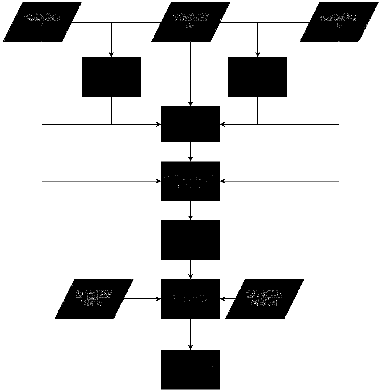
[0024] Specific implementation mode one: combine figure 1 Describe this embodiment, the multi-manifold-based manifold alignment algorithm that maintains the global geometric structure of this embodiment, the specific process is:
[0025] Step 1. Input the spectral matrix X of samples in source image 1, source image 2 and target image s1 ,X s2 ,X t and their spatial coordinates L 1 , L 2 , L 3 , and X s1 ,X s2 The corresponding category label vector Y for each row 1 , Y 2 ;
[0026] Step 2. Calculate X s1 、X t The spatial spectral distance matrix d of 13 , X s2 、X t The spatial spectral distance matrix d of 23 , X s1 、X s2 The spatial spectral distance matrix d of 12 , for each type of sample in the source image, select k samples with the smallest spatial spectral distance in the target image to obtain three sets of data pairs that need to be matched;
[0027] Step 3. Calculate X s1 、X s2 、X t The geodesic distance matrix D s1,s1 、D s2,s2 、D t,t , and u...
specific Embodiment approach 2
[0032] Specific embodiment two: the difference between this embodiment and specific embodiment one is: the calculation of X in the second step s1 、X t The spatial spectral distance matrix d of 13 , X s2 、X t The spatial spectral distance matrix d of 23 , X s1 、X s2 The spatial spectral distance matrix d of 12 , for each type of sample in the source image, k samples with the smallest spatial spectral distance are selected in the target image, and three sets of data pairs that need to be matched are obtained. The specific process is:
[0033]
[0034]
[0035] d 12 = d 12 spectral d 12 spatial
[0036]
[0037]
[0038] d 13 = d 13 spectral d 13 spatial
[0039]
[0040]
[0041] d 23 = d 23 spectral d 23 spatial
[0042] in s1 is the source image 1, s2 is the source image 2, t represents the target image, x s1 i Denotes the ith sample of source image 1, x s2 i Denotes the ith sample of source image 2, x s2 j Denotes the jth sa...
specific Embodiment approach 3
[0046] Specific embodiment three: the difference between this embodiment and specific embodiment one or two is: the calculation of X in the step three s1 、X s2 、X t The geodesic distance matrix D s1,s1 、D s2,s2 、D t,t , and using three sets of data pairs that need to be matched to obtain the distance matrix D of the spectra of different time phase diagrams s1,s2 、D s1,t 、D s2,t ; The specific process is:
[0047] Step 31. Calculate the respective geodesic distance D of the source image and the target image s1,s1 ,D s2,s2 ,D t,t ;
[0048] Step 32. Use three sets of data pairs that need to be matched to obtain the distance matrix D of the spectrum of the phase diagram at different times s1,s2 ,D s1,t ,D s2,t :
[0049]
[0050]
[0051]
[0052] Among them, a j is the first a in the matching data j total number of categories in the source image×k′; b j b in the matching data j , the total number of categories in the source image×k′; a j ,b j means x...
PUM
 Abstract
Description
Claims
Application Information
 - Generate Ideas
- Intellectual Property
- Life Sciences
- Materials
- Tech Scout
- Unparalleled Data Quality
- Higher Quality Content
- 60% Fewer Hallucinations
Browse by: Latest US Patents, China's latest patents, Technical Efficacy Thesaurus, Application Domain, Technology Topic, Popular Technical Reports.
© 2025 PatSnap. All rights reserved.Legal|Privacy policy|Modern Slavery Act Transparency Statement|Sitemap|About US| Contact US: help@patsnap.com


