Finite-element-based computer numerical control bender frame analysis method

An analysis method and finite element technology, applied in the direction of electrical digital data processing, special data processing applications, instruments, etc., can solve the problems of long cycle test equipment, time-consuming and laborious, etc., to shorten the design cycle, save time and cost, and improve Use foreground effects

Inactive Publication Date: 2017-05-31
江苏龙胜机床制造有限公司
View PDF6 Cites 0 Cited by
  • Summary
  • Abstract
  • Description
  • Claims
  • Application Information

AI Technical Summary

Problems solved by technology

However, in the prior art to do this kind of test, the cycle is long, and the test...

Method used


Image

  • Finite-element-based computer numerical control bender frame analysis method

Examples


Embodiment Construction

[0024] In order to deepen the understanding of the present invention, the present invention will be further described below in conjunction with the accompanying drawings and embodiments, which are only used to explain the present invention and do not limit the protection scope of the present invention.

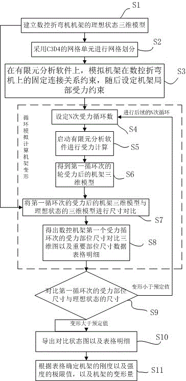
[0025] Such as figure 1 As shown, the analysis method of CNC bending machine frame based on finite element includes the following steps:

[0026] S1, establish the ideal state three-dimensional model of the CNC bending machine frame;

[0027] S2, using C3D4 grid units for grid division;

[0028] S3 On the finite element analysis software, simulate the fixed connection relationship constraints of the frame on the CNC bending machine, and then set the local force constraints of the frame;

[0029] S4-S8, cyclically simulate and calculate the deformation of the rack. After the first N cycles of simulating and calculating the force of the rack, record the deformation size of the...


PUM


Abstract

The invention discloses a finite-element-based computer numerical control bender frame analysis method, comprising the steps of S1, establishing an ideal state three-dimensional model for a computer numerical control bender frame; S2, meshing by a C3D4 mesh unit; S3, simulating on finite element analysis software, fixation-connection relational constraints of the frame on a computer numerical control bender, and setting frame local stress constraints; S4 to S8, performing cycle simulation and calculation on frame deformation; S9, comparing stressed part size in the first cycle to the size in ideal state; S10, exporting a comparison state graph and details of a table; S11 determining frame rigidity and strength limits, well as frame deformation according the table. The analysis method employs finite element analysis software to directly calculate bending and shearing tolerance rigidity and strength and deformation quantities of the computer numerical control frame at different positions, design efficiency of the frame is improved, the test stage time and cost are saved, and the design period is shortened.

Description

technical field [0001] The invention relates to the technical field of a CNC bending machine frame, in particular to an analysis method for a CNC bending machine frame based on finite elements. Background technique [0002] The bending machine is a machine capable of bending thin plates. Its structure mainly includes a bracket, a workbench and a clamping plate. The workbench is placed on the bracket. The workbench is composed of a base and a pressure plate. The base is composed of a seat shell, a coil and a cover plate, the coil is placed in the depression of the seat shell, and the top of the depression is covered with a cover plate. When in use, the wire is energized to the coil, and after energization, an attractive force is generated on the pressure plate, so as to realize the clamping of the thin plate between the pressure plate and the base. Due to the use of electromagnetic force clamping, the pressure plate can be made into a variety of workpiece requirements, and t...

Claims


Application Information

Patent Timeline
IPC IPC(8): G06F17/50
CPCG06F30/17G06F30/23
Inventor 刘明龙
Owner 江苏龙胜机床制造有限公司
Why Eureka
Try Eureka