Photovoltaic module test method and photovoltaic module control method
A technology of photovoltaic modules and testing methods, applied in the monitoring of photovoltaic systems, photovoltaic modules, program control, etc., can solve the problems of power generation power attenuation, delamination, failure, etc., and achieve the effect of easy observation and accelerated aging speed.
- Summary
- Abstract
- Description
- Claims
- Application Information
AI Technical Summary
Problems solved by technology
Method used
Image
Examples
no. 1 example
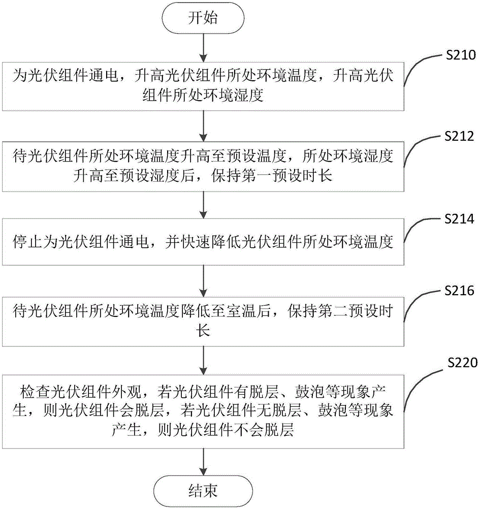
[0026] see figure 1 , the present embodiment provides a method for testing a photovoltaic module, involving a photovoltaic module, the method comprising:
[0027] S210: Power on the photovoltaic module, increase the temperature of the environment where the photovoltaic module is located, and increase the humidity of the environment where the photovoltaic module is located.
[0028] The photovoltaic module should be coupled with the DC power supply, and the power supply should be controlled on and off through the switch. The current passing through the photovoltaic module is 1-15A.
[0029] S212: After the ambient temperature of the photovoltaic module rises to a preset temperature and the humidity of the environment rises to a preset humidity, keep it for a first preset time.
[0030] The preset temperature is 70°C-180°C, the preset humidity is 60%RH-95%RH, and the first preset time is 10min-24h.
[0031] S214: Stop energizing the photovoltaic module, and quickly reduce the...
no. 2 example
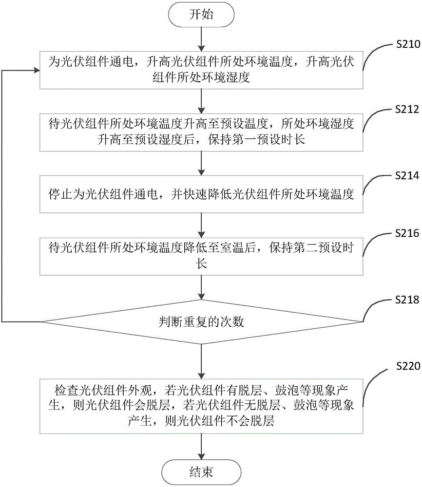
[0038] see figure 2 , the present embodiment provides a method for testing a photovoltaic module, involving a photovoltaic module, the method comprising:
[0039] S210: Power on the photovoltaic module, increase the temperature of the environment where the photovoltaic module is located, and increase the humidity of the environment where the photovoltaic module is located.
[0040] The photovoltaic module should be coupled with the DC power supply, and the power supply should be controlled on and off through the switch. The current passing through the photovoltaic module is 1-15A.
[0041] S212: After the ambient temperature of the photovoltaic module rises to a preset temperature and the humidity of the environment rises to a preset humidity, keep it for a first preset time.
[0042] The preset temperature is 70°C-180°C, the preset humidity is 60%RH-95%RH, and the first preset time is 10min-24h.
[0043] S214: Stop energizing the photovoltaic module, and quickly reduce th...
no. 3 example
[0056] This embodiment provides a control method, which is used in the method for testing the photovoltaic module 110 in the first embodiment.
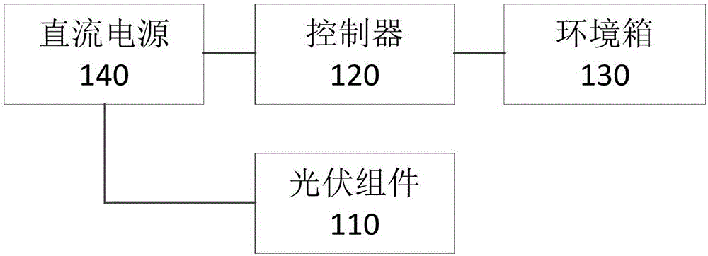
[0057] see image 3 and Figure 4 , the control method involves the photovoltaic module 110 , the controller 120 , the environment box 130 and the DC power supply 140 . The photovoltaic module 110 is coupled to the DC power supply 140 , the controller 120 is coupled to the DC power supply 140 , and the controller 120 is coupled to the environmental box 130 . The controller 120 may be an ARM, a single-chip microcomputer, or the like. The photovoltaic module 110 is located in the environment box 130, and the door of the environment box 130 is closed.
[0058] see Figure 5 , the control methods include:
[0059] S310: The controller 120 controls the DC power supply 140 to supply power to the photovoltaic module 110, and controls the environment box 130 to increase the temperature and humidity.
[0060] The current range of the DC ...
PUM
 Abstract
Description
Claims
Application Information
 - R&D
- Intellectual Property
- Life Sciences
- Materials
- Tech Scout
- Unparalleled Data Quality
- Higher Quality Content
- 60% Fewer Hallucinations
Browse by: Latest US Patents, China's latest patents, Technical Efficacy Thesaurus, Application Domain, Technology Topic, Popular Technical Reports.
© 2025 PatSnap. All rights reserved.Legal|Privacy policy|Modern Slavery Act Transparency Statement|Sitemap|About US| Contact US: help@patsnap.com


