
CMOS sensor-based embedded correction system and correction method thereof

A CMOS sensor, embedded technology, applied in general control systems, control/regulation systems, instruments, etc., can solve the problems that visible light sensors cannot meet comprehensive requirements, poor vibration accuracy, and poor anti-interference ability, making it more convenient to achieve system operation intelligence , the effect of improving precision and accuracy, improving accuracy and reliability

Pending Publication Date: 2017-05-31
CHANGZHOU INST OF OPTOELECTRONICS TECH
View PDF2 Cites 2 Cited by
  • Summary
  • Abstract
  • Description
  • Claims
  • Application Information

AI Technical Summary

Problems solved by technology

The output of the visible light sensor is the switching signal of the offset, which can only indicate whether it is offset and the direction of the offset, which leads to the problems of vibration and low precision in the control; Poor, resulting in a relatively narrow scope of application; Finally, considering that there are inevitably certain defects at the edge of the actual industrial strip, if the strip is corrected for the edge defect, it will be counterproductive and even cause the strip to break
In summary, the existing visible light sensors can no longer meet the comprehensive requirements of actual strip production

Method used


Image

  • CMOS sensor-based embedded correction system and correction method thereof
  • CMOS sensor-based embedded correction system and correction method thereof
  • CMOS sensor-based embedded correction system and correction method thereof

Examples


Embodiment 1

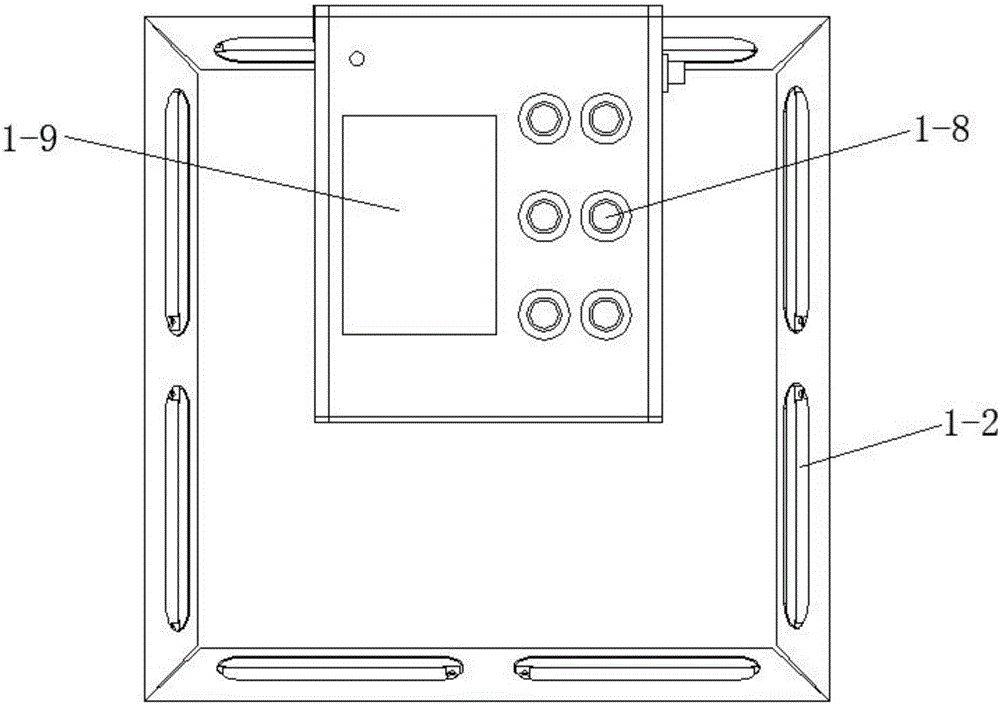
[0029] See Figure 1 to Figure 3 , The embedded deviation correction system based on CMOS sensor in this embodiment includes a deviation correction device 1 and a control box 2 .

[0030] The correction instrument 1 includes a bracket 1-1, a ring light source module 1-2 fixed on the bottom of the bracket 1-1, a housing 1-3 fixed on the upper part of the bracket 1-1 and located above the ring light source module 1-2, and arranged on the housing The STM32 main operation controller 1-4, the first bluetooth module 1-5 and the WiFi module 1-6 in the body 1-3, the CMOS image sensor 1-7 arranged on the lower end surface of the casing 1-3, arranged on the casing The state display on the upper end surface of the body 1-3 and the key control module 1-8 and the TFT liquid crystal display module 1-9. The ring light source module 1-2, the first Bluetooth module 1-5, the WiFi module 1-6, the CMOS image sensor 1-7, the status display and button control module 1-8 and the TFT liquid crystal ...


PUM


Abstract

The invention discloses a CMOS sensor-based embedded correction system and a correction method thereof. The CMOS sensor-based embedded correction system comprises a correction instrument and a control box, wherein the correction instrument comprises a bracket, an annular light source module, a shell, an STM32 main operation controller, a first Bluetooth module, a WiFi module, a CMOS image sensor, a state display and key control module and a TFT liquid crystal display module, wherein the annular light source module is fixed at the bottom of the bracket; the shell is fixed at the upper part of the bracket and located at the upper part of the annular light source module; the STM32 main operation controller, the first Bluetooth module and the WiFi module are arranged in the shell; the CMOS image sensor is arranged on the lower end surface of the shell; the state display and key control module is arranged on the upper end surface of the shell; and a motor drive module and a second Bluetooth module electrically connected with the motor drive module are arranged in the control box. Defect detection can be carried out on the edge of a strip before correction, so that the phenomenon of miscorrection is effectively prevented, the correction accuracy and reliability are improved and the CMOS sensor-based embedded correction system can adapt to comprehensive requirements of actual strip production.

Description

technical field [0001] The invention relates to an embedded deviation correction system and a deviation correction method based on a CMOS sensor. Background technique [0002] At present, visible light sensors, namely photoelectric sensors, are mainly used in domestic deviation correction control systems. Although there have been researches on infrared sensors and CCD sensors, there are not many applications in practice. The output of the visible light sensor is the switching signal of the offset, which can only indicate whether it is offset and the direction of the offset, which leads to the problems of vibration and low precision in the control; Poor, resulting in a relatively narrow scope of application; Finally, considering that there are inevitably certain defects at the edge of the actual industrial strip, if the strip is corrected for the edge defect, it will be counterproductive and even cause the strip to break. To sum up, the existing visible light sensor can no l...

Claims


Application Information

Patent Timeline
IPC IPC(8): G05B19/042
CPCG05B19/0423G05B2219/24215Y02D30/70
Inventor 刘文蒋威傅艳红路超群
Owner CHANGZHOU INST OF OPTOELECTRONICS TECH
Learn More