
Stereoscopic display optical grating and manufacturing method of stereoscopic display optical grating as well as stereoscopic display device

A stereoscopic display, grating technology, applied in optics, optical elements, nonlinear optics, etc., can solve the problems of signal crosstalk, change of light transmission direction of left and right eyes, brightness loss, etc., and achieve the effect of preventing image crosstalk

Active Publication Date: 2017-05-31
WUHAN CHINA STAR OPTOELECTRONICS TECH CO LTD
View PDF5 Cites 10 Cited by
  • Summary
  • Abstract
  • Description
  • Claims
  • Application Information

AI Technical Summary

Problems solved by technology

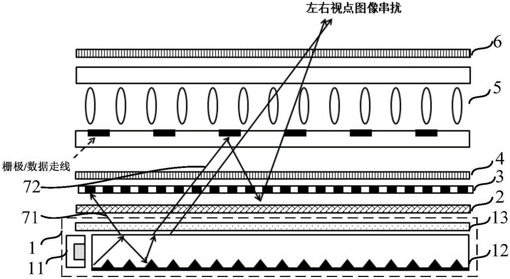
[0005] However, after the polarized light passes through the grating layer 3, due to the blocking of the light-shielding part of the grating layer 3, more than half of the brightness will still be lost
In addition, since the LCD cell 5 contains metal layers for transmitting electrical signals, such as gate lines (Gate) and data lines (Date), etc., although the area ratio of these signal lines is relatively low relative to the entire display panel , but when the left and right eye viewpoint signals passing through the grating are reflected by the metal layer and reflected by other film layers of the backlight module 1, it is easy to change the transmission direction of the left and right eye light rays to form signal crosstalk

Method used


Image

  • Stereoscopic display optical grating and manufacturing method of stereoscopic display optical grating as well as stereoscopic display device
  • Stereoscopic display optical grating and manufacturing method of stereoscopic display optical grating as well as stereoscopic display device
  • Stereoscopic display optical grating and manufacturing method of stereoscopic display optical grating as well as stereoscopic display device

Examples


Embodiment Construction

[0029] The implementation of the present invention will be described in detail below in conjunction with the accompanying drawings and examples, so as to fully understand and implement the implementation process of how to apply technical means to solve technical problems and achieve corresponding technical effects in the present invention. The embodiments of the present application and the various features in the embodiments can be combined with each other under the premise of no conflict, and the formed technical solutions are all within the protection scope of the present invention.

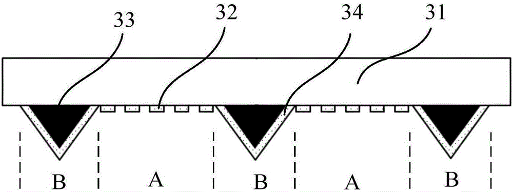
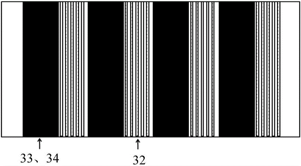
[0030] figure 2 and Figure 3a It is a schematic structural diagram of a three-dimensional display grating according to an embodiment of the present invention, combined with the following figure 2 and Figure 3a This example will be described in detail.

[0031] Such as figure 2 As shown, it is a side view of the three-dimensional display grating in this embodiment, which mainly includes...


PUM


Abstract

The invention discloses a stereoscopic display optical grating and a manufacturing method of the stereoscopic display optical grating as well as a stereoscopic display device. The stereoscopic display optical grating comprises a transparent base, and a light transmitting region and a light shielding region which are arranged on the transparent base at interval, wherein the light transmitting region is internally provided with a metal strip-shaped optical grating for receiving polarized light emitted to the light transmitting region from a backlight module and selecting the polarized light; the light shielding region is internally provided with a black light shielding matrix and a metal light shielding optical grating, wherein the black light shielding matrix is used for absorbing polarized light which is reflected back into the light shielding region from a liquid crystal display unit; the metal light shielding optical grating is used for receiving the polarized light which is emitted to the light shielding region from the backlight module and reflecting the polarized light back to the backlight module, so as to emit the polarized light to the light transmitting region again. The problem in the prior art that the brightness loss is caused by the light shielding effect of the optical grating in an optical grating naked-eye stereoscopic display process is solved; meanwhile, an image crosstalk phenomenon is caused by metal lead wire reflection can be effectively prevented.

Description

technical field [0001] The invention belongs to the technical field of liquid crystal display, and in particular relates to a three-dimensional display grating, a manufacturing method thereof, and a three-dimensional display device. Background technique [0002] People's perception of the objective environment is always obtained through vision, hearing, touch, smell, and taste. Realistically simulating and reproducing these on-the-spot feelings is one of the important research topics of modern science and technology. Stereo vision technology is developed based on this need. [0003] At present, the more popular stereoscopic vision technology is the naked-eye 3D technology, especially the naked-eye 3D technology using gratings. Because it gets rid of complicated auxiliary equipment and can effectively block the image crosstalk between different viewpoints, it has a better stereoscopic effect. display effect. [0004] figure 1 Shown is a schematic structural diagram of a re...

Claims


Application Information

Patent Timeline
Patent Type & Authority Applications(China)
IPC IPC(8): G02B27/22G02F1/1335
CPCG02B30/27G02F1/133512
Inventor 崔宏青查国伟
Owner WUHAN CHINA STAR OPTOELECTRONICS TECH CO LTD
Learn More