
Novel scanning method and novel scanning device of optical resolution photo-acoustic microscope

A technology of photoacoustic microscope and scanning method, which is applied in the direction of material analysis, measuring device and scientific instrument by optical means. The effect of noise ratio

Inactive Publication Date: 2017-05-31
UNIV OF ELECTRONICS SCI & TECH OF CHINA
View PDF4 Cites 22 Cited by
  • Summary
  • Abstract
  • Description
  • Claims
  • Application Information

AI Technical Summary

Problems solved by technology

[0002] At present, when applying optical resolution photoacoustic microscope to image the target object at home and abroad, the most commonly used scanning method is to use the confocal method of point-focused ultrasonic detector and pulsed laser to excite and detect the photoacoustic signal, while using mechanical scanning photoacoustic microscope or the target object to obtain the image of the target object point by point. This scanning method has high requirements on the mechanical scanning motor, and the imaging speed is slow and expensive. In addition, the acceleration and deceleration process of the motor during mechanical scanning and the movement Any vibration will displace the image and affect the image quality
In response to the above problems, many research groups at home and abroad have proposed many solutions, such as the use of high-performance voice coil motors, and the combination of optical scanning and mechanical scanning. These methods have indeed improved the imaging speed and solved the misalignment problem. , but it is difficult to miniaturize, and there is still relative motion between the photoacoustic microscope and the target object, which is inconvenient for some clinical applications
There are two other solutions that use a micro-scanning electron microscope to simultaneously scan the focused laser beam and the sound field, and use a two-dimensional scanning galvanometer system and an unfocused ultrasonic detector to image the target object. These two methods are used in photoacoustic microscopy and There is no relative motion between the target objects, but the effective field of view of the former is very small and the micro-scanning electron microscope is very fragile, and the signal-to-noise ratio of the detected photoacoustic signal is low due to the use of unfocused ultrasonic detectors in the latter, The quality of the collected photoacoustic microscopy images is poor, and the above problems limit the application of optical resolution photoacoustic microscopy

Method used


Image

  • Novel scanning method and novel scanning device of optical resolution photo-acoustic microscope
  • Novel scanning method and novel scanning device of optical resolution photo-acoustic microscope
  • Novel scanning method and novel scanning device of optical resolution photo-acoustic microscope

Examples


Embodiment 1

[0035] Embodiment 1 is the reflective scanning device of the present invention

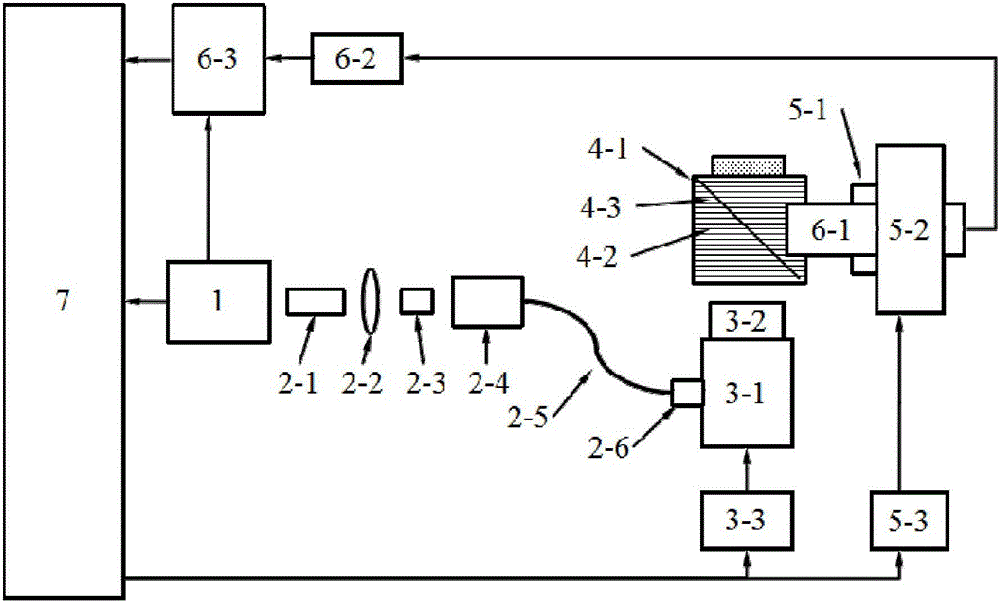
[0036]figure 1 It is a structural schematic diagram of a reflective scanning device, which includes a laser 1, a single-mode fiber coupling component, a two-dimensional scanning galvanometer system, a reflective support tank, an electronically controlled rotary table component, a signal acquisition component, and a computer.

[0037] Among them, the single-mode fiber coupling assembly is composed of a spatial light filter 2-1, a collimating lens 2-2, an objective lens 2-3, and a single-mode fiber coupling adjustment frame 2-4, which are sequentially installed coaxially with the pulse laser 1, and through a single The mode fiber 2-5 and the single-mode fiber collimating lens 2-6 are connected with the two-dimensional scanning vibrating mirror system 3-1; the scanning lens 3-2 is installed on the two-dimensional scanning vibrating mirror 3-1, and the computer 7 passes the scanning The mirror drive c...

Embodiment 2

[0042] Embodiment 2 is the transmissive scanning device of the present invention

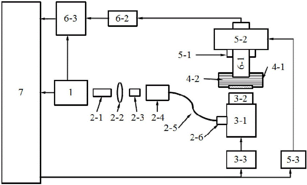
[0043] figure 2 It is a transmissive structure diagram of the device of the present invention, and its components are similar to those in Embodiment 1, the only difference is that a transmissive bracket water tank is used instead of a reflective bracket tank, and through holes are arranged on the upper and lower sides of the transmissive bracket tank, and the bottom The through hole is sealed with a transparent film and used as an imaging interface to ensure light transmission while the internal liquid does not leak. The imaging object is placed in this through hole; the upper through hole is used to place a line-focused ultrasonic detector. The imaging object is attached to the through hole at the bottom of the water tank 4-1 with a medical ultrasonic coupling agent, and the inside of the water tank is filled with an ultrasonic coupling liquid 4-2, and the water tank 4-1 is placed at the focal...


PUM

PropertyMeasurementUnit
Pulse widthaaaaaaaaaa

Abstract

The invention discloses a novel scanning method and a novel scanning device of an optical resolution photo-acoustic microscope, belonging to the technical field of photo-acoustic imaging. The device disclosed by the invention has the working process and working principle that after being collimated by using a single mold optical fiber coupling component, pulse laser emitted from a laser emitter is input into a two-dimensional scanning galvanometer system; the two-dimensional scanning galvanometer system focuses the laser onto a target object to generate a photo-acoustic signal, and a linear area corresponding to a focusing area of a linear focusing ultrasonic detector is scanned; photo-acoustic signals generated in different scanning positions are transmitted to the linear focusing ultrasonic detector through a water tank full of an ultrasonic coupling liquid, and are converted into piezoelectric signals; after being amplified by using an amplifier, the piezoelectric signals are acquired by using a data acquisition card, and are stored in a computer for data processing. The optical resolution photo-acoustic microscope and the target object do not need to move relative to each other, the requirements of the optical resolution photo-acoustic microscope on a signal to noise ratio can be met, and meanwhile, a large view field range and a high resolution can be met.

Description

technical field [0001] The invention belongs to the technical field of photoacoustic imaging, and in particular relates to a novel scanning method and device for optical resolution photoacoustic microscopy. Background technique [0002] At present, when applying optical resolution photoacoustic microscope to image the target object at home and abroad, the most commonly used scanning method is to use the confocal method of point-focused ultrasonic detector and pulsed laser to excite and detect the photoacoustic signal, while using mechanical scanning photoacoustic microscope or the target object to obtain the image of the target object point by point. This scanning method has high requirements on the mechanical scanning motor, and the imaging speed is slow and expensive. In addition, the acceleration and deceleration process of the motor during mechanical scanning and the movement Any vibration will displace the image and affect the image quality. In response to the above pr...

Claims


Application Information

Patent Timeline
IPC IPC(8): G01N21/17
CPCG01N21/1702G01N2021/1706
Inventor 奚磊
Owner UNIV OF ELECTRONICS SCI & TECH OF CHINA
Learn More