
High pressure shielding cycloid pump

A cycloid pump, high pressure technology, applied in the pump, rotary piston/swing piston pump combination, pump components and other directions, can solve the problems of high lift, small flow of booster pump, performance deviation of booster pump, etc. Simple and compact structure, improved reliability, compact structure

Active Publication Date: 2017-05-31
XIAN AEROSPACE PROPULSION INST
View PDF5 Cites 4 Cited by
  • Summary
  • Abstract
  • Description
  • Claims
  • Application Information

AI Technical Summary

Problems solved by technology

The booster pump has a small flow rate and a high head, and is a low specific speed pump. Generally, a positive displacement pump is used to improve the boosting efficiency. Due to the small flow rate of the pump, the axial clearance and radial clearance of the positive displacement pump rotor are relatively large. , Long-term work and wear cause the gap to change, the performance of the booster pump to deviate, and the stability is poor, which affects the reliability of the engine.
In addition, the conventional booster pump has a dynamic seal structure, the system pressure is high, and the reliability of the dynamic seal is poor, which cannot meet the working requirements of the engine for multiple starts and long-term storage

Method used


Image

  • High pressure shielding cycloid pump
  • High pressure shielding cycloid pump
  • High pressure shielding cycloid pump

Examples


Embodiment Construction

[0022] Below in conjunction with accompanying drawing and specific embodiment content of the present invention is described in further detail:

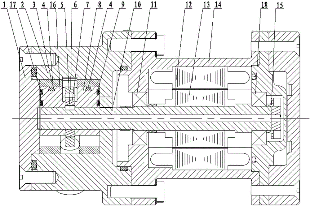
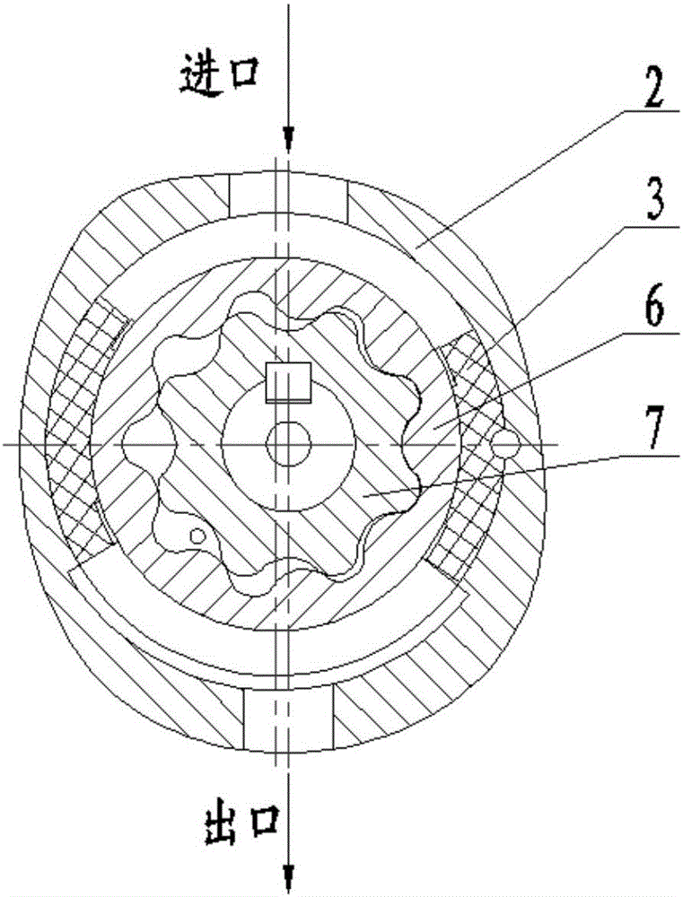
[0023] like figure 1 The high-voltage shielded cycloidal pump shown includes an end cover 1, a housing 2, an epicycloidal rotor 6, an intracycloidal rotor 7, a shaft 10, a left bearing 11, a right bearing 18, a motor housing 14, a motor stator 12, The motor rotor 13 and the position sensor 15; the left bearing 11 and the right bearing 18 are arranged on both sides of the motor rotor 13 to support the rotation of the shaft system. The hypocycloidal rotor 7 is installed on the cantilever end of the shaft 10 through the key 5, and the rotation of the motor rotor 13 drives the inner swing The linear rotor 7 rotates, and the epicycloid rotor 6 and the hypocycloid rotor 7 rotate in the same direction to form a volume alternately changing cavity to realize the process of sucking and pressurizing the liquid medium. The hypocycloid rotor 7 and...


PUM


Abstract

The invention provides a high pressure shielding cycloid pump. The high pressure shielding cycloid pump has small gap flow discharge amount and high stability, is coaxial with a motor and having no dynamic seal. The high pressure shielding cycloid pump comprises an end cap, a shell, an epicycloid rotor, a hypocycloid rotor, a shaft, bearings, a motor stator, a motor rotor and a position sensor; the bearings are arranged at two sides of the motor rotor, the hypocycloid rotor is arranged at the cantilever end of the shaft through a key, the hypocycloid rotor and the motor rotor are respectively connected with the same shaft, a lining is arranged at the inner side of the shell, the lining is in transition fit with the shell, and the lining is eccentrically arranged in the shell; and compensation side plates are arranged at two sides of the hypocycloid and epicycloid rotors, the compensation side plates are positioned at the inner side of the lining, a left side seal and a right side seal are arranged between the compensation side plates and the cover plate and between the compensation side plates and the shell, and the shaft is provided with an axially-penetrating center hole. The technical problems of large gap flow discharge amount, easiness in deviation of performances, poor stability and poor dynamic seal reliability of present cycloid pumps are solved in the invention.

Description

technical field [0001] The invention relates to the field of fluid machinery, in particular to a high-pressure shielded gerotor pump. Background technique [0002] In order to meet the requirements of high performance and low structural weight of aerospace vehicle engines, the booster pump needs to be started multiple times under high system pressure. The main technical problems solved by the pump. The booster pump has a small flow rate and a high head, and is a low specific speed pump. Generally, a positive displacement pump is used to improve the boosting efficiency. Due to the small flow rate of the pump, the axial clearance and radial clearance of the positive displacement pump rotor are relatively large. 1. Long-term working wear causes the gap to change, the performance of the booster pump deviates, and the stability is poor, which affects the reliability of the engine. In addition, the conventional booster pump has a dynamic seal structure, the system pressure is hi...

Claims


Application Information

Patent Timeline
IPC IPC(8): F04C2/10F04C11/00F04C15/00
CPCF04C2/082F04C2/10F04C11/008F04C15/0003F04C15/0088F04C15/0096F04C2270/175
Inventor 王文廷陈晖杜玉洁许开富卜学兵罗鹏李永鹏
Owner XIAN AEROSPACE PROPULSION INST
Learn More