Direct injection gasoline engine combustion system and control method

A combustion system and control method technology, applied in engine control, combustion engines, mechanical equipment, etc., can solve problems such as combustion stability and unfavorable emission results, weakening the flow strength of the mixture, and multiple oil films

Inactive Publication Date: 2017-05-31
TSINGHUA UNIV
View PDF2 Cites 2 Cited by
  • Summary
  • Abstract
  • Description
  • Claims
  • Application Information

AI Technical Summary

Problems solved by technology

This arrangement is easy to produce more oil film in the pit, and is not conducive to the volatilization of oil film
Studies have shown that oil film is the main source of particulate matter in direct injection gasoline engines, so the combustion chamber shape is not conducive to reducing particulate matter emissions
In addition, some pistons do not have guide surfaces, and only retain a wider combustion chamber pit. Although it helps to reduce the formation of oil film, it is not conducive to the gas flow and oil-gas mixing in the combustion chamber, weakening the flow strength of the mixed gas, and affecting combustion stability. and emissions results are unfavorable

Method used


Image

  • Direct injection gasoline engine combustion system and control method
  • Direct injection gasoline engine combustion system and control method

Examples


no. 1 example

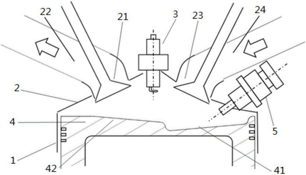
[0026] In the first embodiment of the present invention, the combustion control of the engine adopts two fuel injection strategies. When the first injection time is between 240°CA and 300°CA before the compression top dead center, the second injection time is between 120°CA and 300°C before the compression top dead center. Between 180°C and CA; the fuel ratio of the first injection is 60% to 90%, the fuel ratio of the second injection is 10% to 40%, and the sum of the fuel ratio of the two injections is 100%.

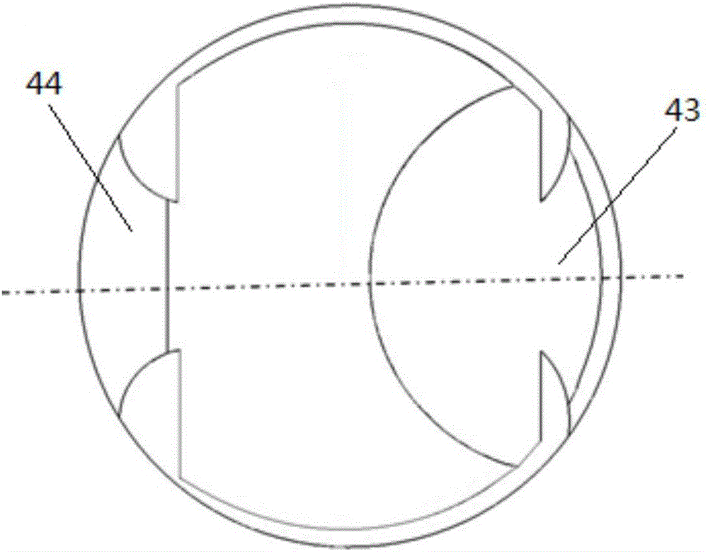
[0027] In the first embodiment, when the fuel injector 5 injects oil for the first time, the oil beam will touch the first dimple 41 , and when the fuel injector 5 injects fuel for the second time, the oil beam will only touch the second dimple 42 . Since there is no protrusion on the piston of the traditional direct-injection gasoline engine between the first pit and the second pit, it will not hinder the airflow movement on the piston surface, which is beneficial to th...

no. 3 example

[0029] In the third embodiment of the present invention, the combustion control of the engine adopts a three-time fuel injection strategy. between ℃CA; the third injection time is between 120℃CA and 150℃CA before compression top dead center; The ratio is 5% to 20%, and the sum of the fuel ratios of the three injections is 100%.

[0030] According to the compression ratio of different engines, the size of the combustion chamber, the law of intake and exhaust, and the fuel injection law of the injector, the injection timing, injection pulse width, injection pressure and ignition timing should also be optimized accordingly to achieve the best results.

[0031] The direct-injection gasoline engine combustion system and control method described in the present invention can stabilize combustion, accelerate combustion, and can effectively reduce the generation of particulate matter, and can reduce fuel consumption and emissions at the same time, and realize technical upgrading of exi...


PUM


Abstract

The invention provides a direct injection gasoline engine combustion system and a control method. The system comprises a cylinder body, a cylinder cover, a spark plug, a piston and an oil injector; an intake valve and an intake way connected with the intake valve are arranged on one side of the cylinder cover, and an exhaust valve and an exhaust way connected with the exhaust valve are arranged on the other side; the head part, positioned in the cylinder body, of the piston is provided with a first pit and a second pit; the first pit and the second pit are directly connected by a smooth surface; and the first pit is deeper than the second pit to guarantee no projection part. The system can guarantee the ignition stability in an ignition mode and reduce particles, and meanwhile, guarantees better engine oil consumption, emission and power performance.

Description

technical field [0001] The invention relates to the field of engines, more specifically, to a combustion system and a control method of a direct-injection gasoline engine. Background technique [0002] At present, compared with traditional gasoline engines, direct injection gasoline engines have the potential of greatly saving energy and reducing HC emissions, and have become the mainstream products of gasoline engines. However, the particulate matter emission of direct injection gasoline engine is higher than that of traditional gasoline engine, which increases the difficulty of meeting emission regulations. Therefore, it is necessary to optimize the combustion system and combustion method from the source to reduce the particulate matter emission of direct injection gasoline engine. [0003] Judging from the characteristics of the combustion system of direct injection gasoline engines produced by major domestic and foreign automobile companies, the compression ratio is roug...

Claims


Application Information

Patent Timeline
IPC IPC(8): F02B23/10F02F3/26F02D37/02
CPCF02B23/10F02D37/02F02F3/26Y02T10/12
Inventor 帅石金赵洪雪王志马骁王步宇静大亮董哲林
Owner TSINGHUA UNIV
Why Eureka
Try Eureka