
Double-layer composite type aeration machine

A composite aerator technology, applied in water aeration, sustainable biological treatment, water/sludge/sewage treatment, etc., can solve the problem of inability to deep aeration, low aeration efficiency, and inconspicuous fragmentation of air bubbles And other issues

Pending Publication Date: 2017-05-31
CHONGQING VOLIK ENVIRONMENTAL PROTECTION EQUIP CO LTD
View PDF9 Cites 1 Cited by
  • Summary
  • Abstract
  • Description
  • Claims
  • Application Information

AI Technical Summary

Problems solved by technology

Although the overall structure of the submersible aerator is relatively simple, easy to maintain, good bubble fragmentation effect, and high aeration efficiency, it can only be used for oxygenation and aeration in specific sewage treatment pools. For some occasions such as ponds, soft The aeration cannot be placed on the river bed, etc., and the aeration depth is relatively shallow. Similarly, although the inverted umbrella aerator has a simple structure and a large service area, it cannot aerate deeply, the bubble fragmentation is not obvious, and the aeration efficiency is not high. Chinese patent application number: 201310578930.0, discloses a turbine aerator, including a controller, a motor, a frame, a height adjustment device, a main shaft and an impeller, and the control signal output terminal of the controller is connected with the control signal of the motor The input end is connected, the frame is connected to the ground on the pool through the height adjustment device, the lower part of the motor is provided with a reduction box, and the rotating shaft of the motor is connected to the main shaft after passing through the reduction box. The lower end of the main shaft is connected with the impeller, and the impeller is located under the water surface in the pool

Method used


Image

  • Double-layer composite type aeration machine

Examples


Embodiment Construction

[0010] The technical solutions of the present invention will be further described below in conjunction with the accompanying drawings and preferred embodiments.

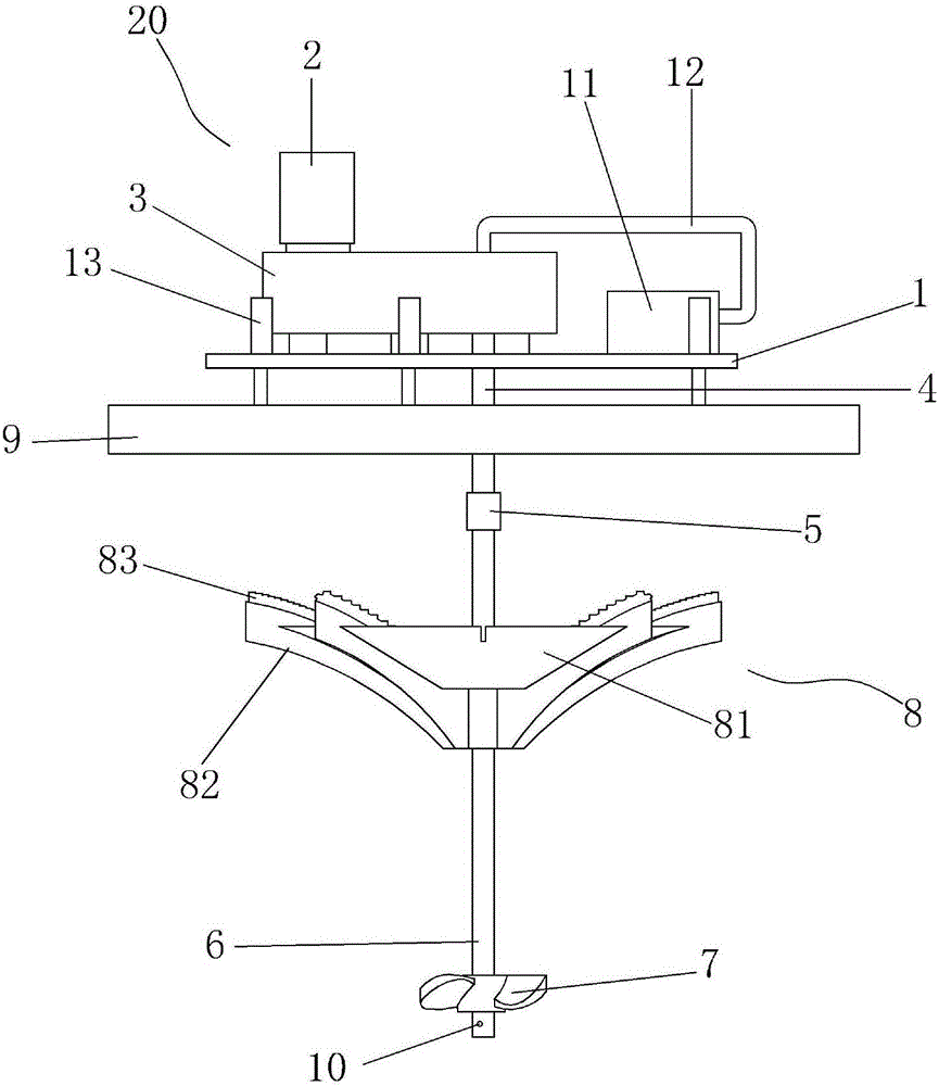
[0011] Such as figure 1 As shown, a double-layer composite aerator according to the present invention includes a base 1, and the base 1 is provided with a hydraulic propulsion device 20 composed of a motor 2 and a reducer 3, and the reducer 3 is provided with a reducer output The shaft 4 and the output shaft 4 of the reducer are connected to the main shaft 6 through a coupling 5, and the main shaft 6 is provided with an air guide cavity (not shown in the drawings), and the lower part of the main shaft 6 is provided with a spiral thrust piece 7 and an air hole 10. An inverted umbrella impeller 8 is provided on the upper part of the main shaft 6, and a compressed air pump 11 is provided on the base 1. The compressed air pump 11 is connected with an air guide tube 12, and the air guide tube 12 is inserted into the air g...


PUM


Abstract

The invention discloses a double-layer composite type aeration machine. The double-layer composite type aeration machine comprises a base, wherein a hydraulic propulsion device is arranged on the base and consists of a motor and a speed reduction mechanism; an output shaft of a speed reducer is arranged in the speed reducer; the output shaft of the speed reducer is connected with a main shaft through a coupling; an air guide cavity is arranged in the main shaft; a spiral flow pushing sheet and an air hole are arranged at the lower part of the main shaft; an inverted umbrella-shaped wheel is arranged at the upper part of the main shaft; a compressed air pump is arranged on the base and is connected with an air guide pipe; the air guide pipe is inserted into the air guide cavity of the main shaft. The double-layer composite type aeration machine has the advantages that the structure is simple, and the installation is convenient; by using the spiral flow pushing sheet as the main propulsion source, the aeration propulsion efficiency is greatly improved; by arranging the spiral flow pushing sheet, the water body is pushed by the spiral flow pushing sheet to flow up at high speed, and by matching with the inverted umbrella-shaped impeller at the water surface, the water body is pushed outwards and rotationally by the inverted umbrella-shaped impeller, so as to greatly improve the aeration efficiency.

Description

technical field [0001] The invention relates to a double-layer composite aerator with reasonable structure, high efficiency, low energy consumption and deep aeration depth. Background technique [0002] The aerator is an important sewage treatment equipment. Its function is mainly to improve the quality of sewage by filling oxygen into the sewage to increase the oxygen content in the water. At present, submersible aerators and inverted umbrella aerators are generally used in the domestic market as the main equipment for aeration and oxygenation. Although the overall structure of the submersible aerator is relatively simple, easy to maintain, good bubble fragmentation effect, and high aeration efficiency, it can only be used for oxygenation and aeration in specific sewage treatment pools. For some occasions such as ponds, soft The aeration cannot be placed on the river bed, etc., and the aeration depth is relatively shallow. Similarly, although the inverted umbrella aerator ...

Claims


Application Information

Patent Timeline
IPC IPC(8): C02F7/00
CPCC02F7/00Y02W10/10
Inventor 陈文
Owner CHONGQING VOLIK ENVIRONMENTAL PROTECTION EQUIP CO LTD
Learn More