
Parallel steel wire winding device

A technology of winding device and steel wire, which is used in transportation and packaging, transportation of filamentous materials, and processing of thin materials, etc. It can solve the problems of limited volume of the reel, limit the winding length of the steel wire, and the winding of the steel wire, so as to improve the adjustment flexibility. , Improve the effect of winding length

Active Publication Date: 2017-05-31
HUAQIANG FANGTE WUHU CULTURE TECH CO LTD
View PDF5 Cites 14 Cited by
  • Summary
  • Abstract
  • Description
  • Claims
  • Application Information

AI Technical Summary

Problems solved by technology

[0003] In the prior art, the same steel wire reel is used to rewind two steel wires at the same time. Due to the limited volume of the reel, even if two sub-guide wheels are used to wind the two steel wires on different sides of the reel respectively, when the steel wire If the length is too long, it will also cause the steel wire to wind and interfere in the reel, which limits the winding length of the steel wire

Method used


Image

  • Parallel steel wire winding device

Examples


Embodiment Construction

[0014] In order to make the technical means, creative features, goals and effects achieved by the present invention easy to understand, the present invention will be further elaborated below.

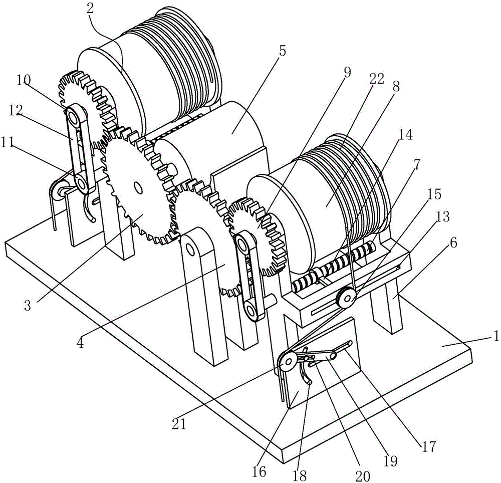
[0015] Such as figure 1 As shown, a side-by-side steel wire winding device includes a bottom plate 1, and a lifting frame 2 is respectively provided on the left and right sides of the bottom plate 1, the lifting frame 2 on the left is driven by a driving gear 3, and the lifting frame 2 on the right is driven by The driven gear 4 meshed with the driving gear 3 is driven, and the driving gear 3 is connected with a motor 5 .

[0016] Described elevating frame 2 comprises installation frame body 6, and described installation frame body 6 middle part is longitudinally provided with a lead screw 7, and installation frame body 6 top longitudinally is equipped with a cylinder 8, and the axis of described cylinder body 8 can be installed in frame body 6 Rotate upward, the front end of the shaft...


PUM


Abstract

The invention relates to a parallel steel wire winding device. The parallel steel wire winding device comprises a bottom plate, two lifting frames are arranged on left and right sides of the bottom plate respectively, the left lifting frame is driven by a driving gear, the right lifting frame is driven by a driven gear meshed with the driving gear, and a motor is connected with the driving gear. Each lifting frame comprises a mounting frame, wherein a lead screw is longitudinally arranged in the middle of the mounting frame, a drum is longitudinally mounted on the upper portion of the mounting frame, a shaft of the drum is capable of rotating on the mounting frame, the front end of the shaft of the drum penetrates the mounting frame to sequentially sleeve a transmission wheel and a driving belt wheel, the front end of the lead screw penetrates the mounting frame to sleeve a driven belt wheel, and a timing belt is connected between the driving belt wheel and the driven belt wheel. By the means that one steel wire is driven by one winding drum to realize steel wire winding, steel wire winding length is greatly increased, and interference of two steel wires under the condition of excessive steel wire winding quantity is avoided. In addition, a second wheel is mounted in a way that a supporting position and a steel wire winding wrap angle of a first wheel are adjustable.

Description

technical field [0001] The invention relates to the technical field of steel wire winding equipment, in particular to a parallel steel wire winding device. Background technique [0002] When performing fairy tales or sci-fi dramas in theaters, it is often necessary to use props to cooperate with actors to perform. Actors use wire equipment to perform suspended performances, and props also need to be suspended with steel wires to cooperate with actors' performances. During the equipment suspension process, two steel wires are required to be suspended together, otherwise it is easy to cause the props to tilt and rotate [0003] In the prior art, the same steel wire reel is used to rewind two steel wires at the same time. Due to the limited volume of the reel, even if two sub-guide wheels are used to wind the two steel wires on different sides of the reel respectively, when the steel wire If the length is too long, it will also cause the steel wire to wind and interfere in the...

Claims


Application Information

Patent Timeline
Patent Type & Authority Applications(China)
IPC IPC(8): B65H54/74B65H54/20B65H59/14
CPCB65H54/20B65H54/74B65H59/14B65H2701/36B65H2408/23B65H2403/421Y02P70/10
Inventor 陈祖尧李乾程曹伟生
Owner HUAQIANG FANGTE WUHU CULTURE TECH CO LTD
Learn More