
A paper wrapping machine

A paper bag and frame technology, applied in the field of paper bag machines, can solve problems such as carton bending, pneumatic paging device limited response speed of pneumatic parts, cardboard pushing device reasoning is not constant, etc.

Active Publication Date: 2019-05-03
广州市万世德智能装备科技有限公司
View PDF5 Cites 0 Cited by
  • Summary
  • Abstract
  • Description
  • Claims
  • Application Information

AI Technical Summary

Problems solved by technology

[0004] For the above-mentioned paper wrapping machine, in order to realize automatic packaging, since the paper loading device needs to be conveyed one by one, in order to reliably convey the cardboard, the cardboard in the cardboard warehouse must be pushed forward one by one. The reasoning of the existing cardboard pushing device is not constant. Not adjustable, and inconvenient to add cardboard
[0005] In the process of bottle driving, in the past, the overload clutch was installed on the drive shaft or directly monitored by the servo motor. This method has a slow response speed and the reliability of explosion-proof bottles is not high.
[0006] In the process of cardboard folding, the side of the carton is traditionally folded by the side folding mechanism, and the top is realized by the forced forming of the guide rod or the pneumatic flapping device. The forming of the guide rod will cause the carton to bend, which is prone to jamming. The pneumatic discharge The page device is limited by the response speed of the pneumatic parts, so it is not suitable for high-speed paper wrapping machines

Method used


Image

  • A paper wrapping machine
  • A paper wrapping machine
  • A paper wrapping machine

Examples


Embodiment Construction

[0031] The present invention will be further described in detail below in conjunction with the accompanying drawings and specific embodiments.

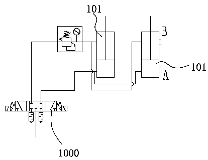
[0032] Such as figure 1 with figure 2 As shown, a paper wrapping machine includes a frame 1, on which a bottle feeding conveying device 2, a bottle separating device 3, a cardboard warehouse 4, a paper loading device 5, a bottle driving device 6, and a side folding device 7 are arranged. , Press box forming device 8, pneumatic constant pressure paper pushing device 9, bottle anti-jamming device 10 and mechanical clapping device 11.

[0033] The bottle feeding conveying device 2, the bottle separating device 3, the bottle driving device 6, the mechanical clapping device 11, the side folding device 7, and the pressing box forming device 8 are arranged in sequence according to the conveying direction. The cardboard bin 4 is located below the bottle feeding conveying device 2 , and the paper loading device 5 is at the output end of the...


PUM


Abstract

The invention discloses a paper packaging machine comprising a rack, wherein a bottle conveying device, a bottle allocating device, a paperboard bin, a paper feeding device, a bottle driving device, a side face folding device and a press box forming device are arranged on the rack; a pneumatic constant pressure paper pushing device is installed at the paperboard bin, the pneumatic constant pressure paper pushing device comprises a paper pushing upright column, a paper pushing frame, a paper pushing transmission mechanism, a paper pushing slide block, a stop lever and a locking cylinder component; a bottle clamping prevention device is arranged on a bottle moving frame, and the bottle clamping prevention device comprises a cylinder, a sliding seat, a slide rail and a chain guide block; a mechanical page taking device is arranged between the bottle driving device and the press box forming device; and the mechanical page taking device comprises a transmission mechanism, a connecting plate, a driving shaft, a front connecting rod, a connecting rod, a back connecting rod, a page taking frame and a page taking plate. By adoption of the structure of the paper packaging machine disclosed by the invention, constant thrust can be provided for the paperboard in the paperboard bin so as to ensure the paper feeding device to stably convey the paperboard. Bottle explosion or overload damage of parts caused by bottle clamping in a bottle moving process can be avoided. High-speed page taking action can be realized.

Description

technical field [0001] The present invention relates to a paper wrapping machine. Background technique [0002] The paper wrapping machine is a fully automatic packaging machine that packs glass bottles, pop cans and other similar containers in groups with single-piece cardboard. The machine has a compact structure and a friendly operation interface, and it can realize the fully automatic packaging process in the automatic mode. It is suitable for secondary packaging of products in industries such as beverages, beer, and daily chemicals. [0003] The basic working principle of the wrapping machine is: the container is conveyed to the bottle separating device through the bottle feeding conveying device, and the multiple containers are grouped by the bottle separating device and conveyed forward to the bottle driving device. Sheet conveying, the grouped containers are conveyed to the conveyed cardboard through the bottle driving rod of the bottle driving device, the cardboar...

Claims


Application Information

Patent Timeline
Patent Type & Authority Patents(China)
IPC IPC(8): B65B43/18B65B43/26B65B21/00
CPCB65B21/00B65B43/185B65B43/265
Inventor 刘远强杜伟栋戴伟学
Owner 广州市万世德智能装备科技有限公司
Learn More