
A snow tire groove with a bionic non-smooth pattern

A snow tire, non-smooth technology, applied to tire parts, tire tread/tread pattern, transportation and packaging, etc., can solve the problem of rough structure, no shape feature ratio, no improvement of tire heat dissipation performance and service life, etc. question

Inactive Publication Date: 2018-08-17
JILIN UNIV
View PDF9 Cites 0 Cited by
  • Summary
  • Abstract
  • Description
  • Claims
  • Application Information

AI Technical Summary

Problems solved by technology

In the choice of tread pattern, the bionic design of imitation coral pattern is adopted. When the road is dry, the tread of the tire will automatically harden to reduce wear and noise, and when the road is wet, the tire will become soft again, so as to Improving the grip of tires, but many technical aspects cannot be solved at present
Chinese patent CN103332071A discloses a noise-reducing tire pattern groove. The concave-convex damping structure can eliminate a certain range of air flow frequency in the tube cavity, reduce air pump noise, and reduce the probability of air column resonance, but the structure is relatively rough and has no shape feature ratio. Cannot optimize noise reduction
Chinese patent CN105270102A discloses a streamlined longitudinal groove structure, which can reduce noise, improve the flow of water in the road area, and increase the grip of the tire by increasing the ground contact area under the condition of certain wear and tear of the tire, but the heat dissipation performance of the tire and service life has not been improved
Therefore, there is currently no effective method for reducing tire noise and improving the service life of tires under the condition of slightly modifying the existing tire pattern.

Method used


Image

  • A snow tire groove with a bionic non-smooth pattern
  • A snow tire groove with a bionic non-smooth pattern
  • A snow tire groove with a bionic non-smooth pattern

Examples


Embodiment Construction

[0027] Specific embodiments of the present invention will be further described below in conjunction with the accompanying drawings.

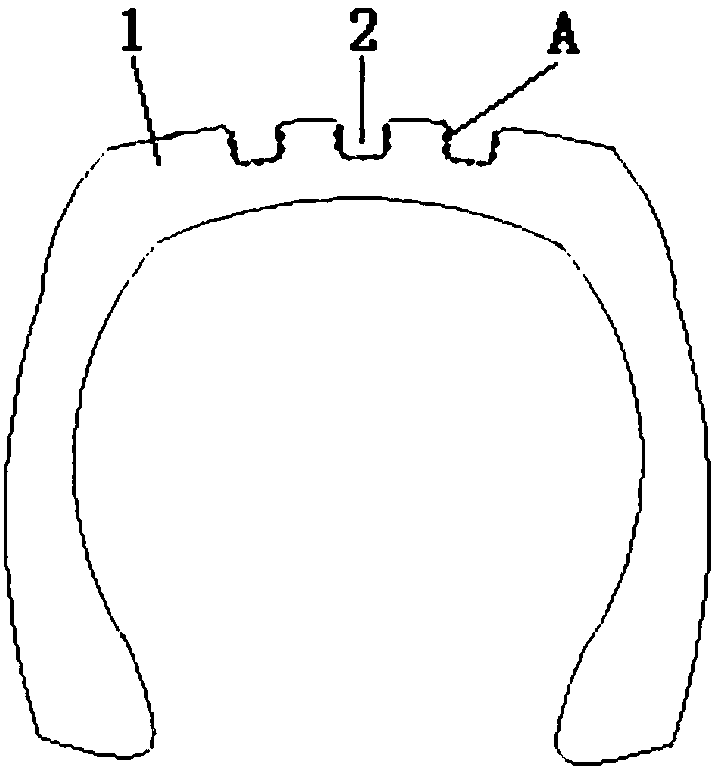
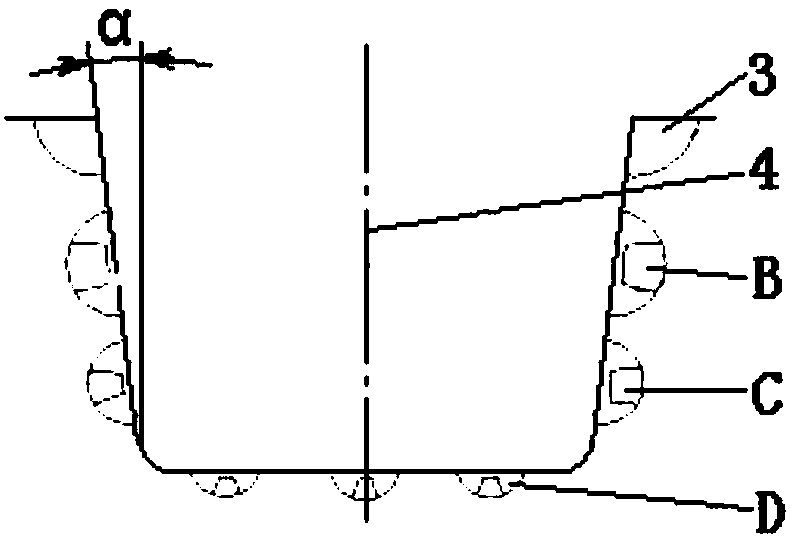
[0028] Such as figure 1 As shown, the cross section of the groove 2 is U-shaped, the depth is 6-16mm, the bottom width is 5-12mm, the angle between the side wall of the groove 2 and the longitudinal axis of the vertical tread is 0-5°, the groove 2 The side wall and the bottom of the groove are arc-shaped.

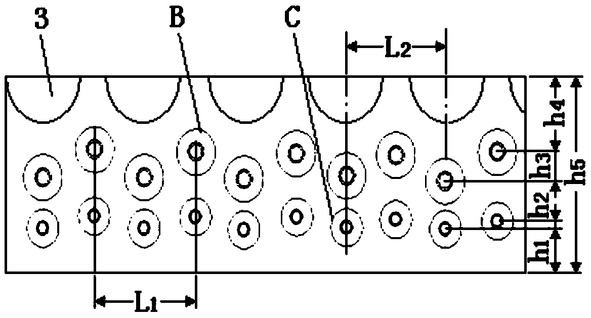
[0029] Such as figure 2 , 5 As shown, the bionic non-smooth pattern A is composed of a hemispherical pit 3, a concave-convex structure IB, a concave-convex structure IIC, and a concave-convex structure IIID. The radius of the hemispherical pit 3 is r 1 1.5-4mm; the bionic non-smooth pattern A on both sides of the groove 2 is distributed symmetrically with respect to the longitudinal axis I4.

[0030] Such as image 3 As shown, the hemispherical pit 3 of the bionic non-smooth pattern A on one side of the groove 2, the concave-convex stru...


PUM


Abstract

The invention relates to a snow tire groove with bionic non-smooth patterns, which belongs to the technical field of auto tires. The bionic non-smooth patterns at two side faces of the snow tire groove are distributed symmetrically; hemispheric pits, concave-convex structures I and concave-convex structures II are sequentially arranged from top to bottom; the three concave-convex structures I and the three concave-convex structures II are arranged under each two adjacent hemispheric pits; the concave-convex structures I and the concave-convex structures II at two sides are in one vertical line with a center of each two adjacent hemispheric pits; each two adjacent concave-convex structure I and the concave-convex structure II are arranged in a staggering way up and down; a middle row, a left row and a right row of a concave-convex structure III arranged on the bottom face of the groove are arranged in a staggering way. The pattern groove provided by the invention can be applied in a snow and four-season car tire, and other pattern structures of the tire have no need to be changed, but a groove structure of the tire needs to be changed, so that the combination properties of an original tire such as drainage and ageing resistance are ensured; the road holding of the tire is improved, the aerodynamic noise of the patterns can be reduced by 3 to 6 percent, stone and sediment can be automatically extruded and discharged, the damage of stones on the tire is effectively prevented, and the service life of the tire is prolonged.

Description

technical field [0001] The invention belongs to the technical field of automobile tires, in particular to a bionic non-smooth pattern of snow tire grooves. Background technique [0002] When driving in winter, a layer of water film will be formed between the tire and the ice and snow road surface, which will reduce the friction between the tire and the road surface and cause the tire to slip. Adhesion to ice and snow roads, so that the tires have stronger grip and anti-skid performance on ice and snow roads, improving braking and handling performance, but at the same time the noise of the tires increases and the wear resistance decreases. The implementation of the EU Tire Labeling Law and my country's "Green Tire Technical Specifications" have put forward clear requirements and limit levels for tire noise performance. In the face of increasingly stringent regulatory requirements, it is imminent to study new technologies for low-noise performance tires. However, the sound m...

Claims


Application Information

Patent Timeline
Patent Type & Authority Patents(China)
IPC IPC(8): B60C11/12
CPCB60C11/1204B60C11/1259B60C11/1272
Inventor 毛春昱马云海李俊伟陈创发王慧鑫肖杨
Owner JILIN UNIV
Learn More