
Automatic pad printing machine

A pad printing machine and automatic technology, applied in the field of printing pad printing machines, can solve the problems of low quality and efficiency, high labor intensity, long cleaning time, etc., and achieve the effect of effective contact adsorption force, maintenance operation, and flexible printing.

Active Publication Date: 2017-05-31
东莞市众泰自动化设备有限公司
View PDF4 Cites 4 Cited by
  • Summary
  • Abstract
  • Description
  • Claims
  • Application Information

AI Technical Summary

Problems solved by technology

During the printing process, the worker needs to place the shell on the printing receiving table, and transfer it to the conveyor belt after printing. When the printing volume is large, the worker must repeatedly place the product and transfer the product, and the labor intensity is relatively high. , the action is relatively single, and at the same time, for the printing of objects such as edges, multi-sided printing or slopes, complex adjustment mechanisms are required in existing equipment
Moreover, during the use of the pad printing machine, there is dust on the objects and between the air. When producing a certain period of time or producing a certain quantity, the rubber head must be cleaned manually, otherwise the products printed later will easily produce defective products; And the cleaning time is long, the quality and efficiency are very low

Method used


Image

  • Automatic pad printing machine
  • Automatic pad printing machine
  • Automatic pad printing machine

Examples


Embodiment Construction

[0017] The present invention is further described below:

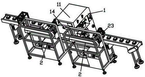
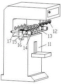
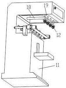
[0018] refer to Figure 1-5 , an automatic pad printing machine, including a transfer platform 2 and a printing mechanism 1, the printing mechanism includes a pad printing body 11, a pad printing rubber head 12 and a cleaning rubber cloth 13, and the pad printing rubber head 12 and cleaning rubber cloth 13 is set opposite to each other, and the two ends of the cleaning adhesive cloth 13 are respectively equipped with a retractable roller 14, an adjustment seat 15, a rotating motor 16 and a horizontal adjustment rod 17. The center of the adjustment seat 15 is hollowed out, and the horizontal adjustment rod 17 passes through the The adjustment seat 15 moves back and forth relative to the adjustment seat; the rotating motors 16 are respectively fixed with the ends of the horizontal adjustment rods 17, and the retractable rollers 14 are connected with the rotating motor 16, and are driven by the rotating motor 16 to retrac...


PUM


Abstract

The invention discloses an automatic pad printing machine. The automatic pad printing machine comprises a transfer platform and a printing mechanism. An extending-retracting roller wheel, a rotating motor and a horizontal adjusting rod are arranged at the two ends of cleaning adhesive tape of the printing mechanism. The extending-retracting roller wheel is driven to rotate through the rotating motor. The transfer platform comprises a horizontal movement mechanism, a movable motor, a movable platform and a workpiece fixture. The workpiece fixture is driven to horizontally move through the horizontal movement mechanism. The movable motor drives the horizontal movement mechanism to move below a pad printing rubber head. The horizontal movement mechanism comprises a rotating motor and a multifunctional rotating disc, and the multifunctional rotating disc is driven to rotate through the rotating motor so that the direction can be adjusted. The automatic pad printing machine is divided into the transfer platform and the printing mechanism; the transfer platform can rotate in a plurality of directions so as to drive a workpiece, and flexible printing is achieved; and the printing mechanism uses the horizontal adjusting rod to adjust the position of the cleaning adhesive tape, so that the cleaning adhesive tape corresponds to the position of the above pad printing rubber head, and direct cleaning is convenient.

Description

technical field [0001] The invention relates to the field of machinery, especially pad printing machines for printing. Background technique [0002] Pad printer is a kind of printing equipment, suitable for plastic, toys, glass, metal, ceramics, electronics, IC packaging, etc. Pad printing is an indirect concave rubber head printing technology. Because the pad printing machine can do up to 12 color registers, the ink layer is very thin and easy to print, very good color expression and printing adaptability, etc. A main method of printing and decorating the surface of an object. During the printing process, the worker needs to place the shell on the printing receiving table, and transfer it to the conveyor belt after printing. When the printing volume is large, the worker must repeatedly place the product and transfer the product, and the labor intensity is relatively high. , the action is relatively simple, and at the same time, for the printing of objects such as edges, m...

Claims


Application Information

Patent Timeline
IPC IPC(8): B41F17/00B41F35/00
CPCB41F17/001B41F35/00
Inventor 贾锦育贾源润贾贵惠贾锦文贾金霖贾金壁
Owner 东莞市众泰自动化设备有限公司
Learn More