
Photovoltaic assembly trimming device

A technology of edge trimming device and photovoltaic module, which is applied in metal processing and other directions, can solve the problems of high working cost, increased production cost, and poor EVA removal effect, and achieve the effects of novel structure, increased edge trimming efficiency, and increased working speed

Active Publication Date: 2017-05-31
礼德新能源江苏有限公司
View PDF6 Cites 3 Cited by
  • Summary
  • Abstract
  • Description
  • Claims
  • Application Information

AI Technical Summary

Problems solved by technology

[0003] Most of the edge trimming technology currently used is to manually remove the overflowing EVA with a utility knife, but in the process of trimming, the utility blade is easy to break, and the broken blade is easy to cause injury to the staff. At the same time, manual trimming The work efficiency is low, the work cost is high, and the removal effect on EVA is poor. At the same time, the edge trimming machine currently in use still needs manual operation. At the same time, the size adaptability of the edge trimming device is poor, and it cannot be mass-produced, which in turn causes production costs. At the same time, some edge trimming devices only have a set of edge trimming knives, and the four sides of the EVA are removed by rotating the photovoltaic module. This working method will result in long processing procedures and low processing efficiency.

Method used


Image

  • Photovoltaic assembly trimming device
  • Photovoltaic assembly trimming device

Examples


Embodiment Construction

[0016] The following will clearly and completely describe the technical solutions in the embodiments of the present invention with reference to the accompanying drawings in the embodiments of the present invention. Obviously, the described embodiments are only some, not all, embodiments of the present invention. Based on the embodiments of the present invention, all other embodiments obtained by persons of ordinary skill in the art without making creative efforts belong to the protection scope of the present invention.

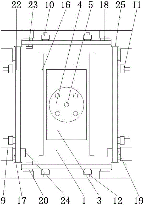
[0017] see figure 1 , in an embodiment of the present invention, a photovoltaic module trimming device, including a workbench 1, a support leg 2 is provided on the lower side of the workbench 1, a mounting groove 3 is opened in the middle of the workbench 1, and a bottom hydraulic cylinder is provided at the bottom of the installation groove 3 Mounting base 6, bottom hydraulic cylinder mounting base 6 is fixedly connected with bottom electro-hydraulic cylinder...


PUM


Abstract

The invention discloses a photovoltaic assembly trimming device which comprises a workbench. An installation groove is formed in the middle of the workbench. A bottom hydraulic cylinder installation seat is arranged at the bottom of the installation groove. The upper side of a bottom electric hydraulic cylinder is connected with a supporting frame through a piston. Vacuum suction cups are arranged on the supporting frame. A vacuum pump is arranged on the lower right side of the workbench. Photovoltaic assembly conveying belts are arranged on the two sides of the installation groove. A left side trimming device is arranged on the upper side of a left side positioning device. A rear side trimming device is arranged on the upper side of a rear side positioning device. A right side trimming device is arranged on the upper side of a right side positioning device. A front side trimming device is arranged on the upper side of a front side positioning device. The photovoltaic assembly trimming device is novel in structure, by arranging four sets of trimming tools, EVA trimming removal can be conducted on the four edges of a photovoltaic assembly at the same time, and the trimming efficiency of the photovoltaic assembly is improved; and meanwhile, the positioning devices are arranged, photovoltaic assemblies of different dimensions can be positioned, the sizes of the photovoltaic assemblies can be judged, the dimension requirements of the different photovoltaic assemblies can be met, and the working speed of trimming is increased.

Description

technical field [0001] The invention relates to the technical field of photovoltaic module production, in particular to a photovoltaic module edge trimming device. Background technique [0002] After the photovoltaic modules are laminated, the packaged EVA usually overflows, and the pulleys remain unchanged for the subsequent framing process. Therefore, the overflowing EVA needs to be removed before framing, that is, the edges of the photovoltaic modules should be trimmed. [0003] Most of the edge trimming technology currently used is to manually remove the overflowing EVA with a utility knife, but in the process of trimming, the utility blade is easy to break, and the broken blade is easy to cause injury to the staff. At the same time, manual trimming The work efficiency is low, the work cost is high, and the removal effect on EVA is poor. At the same time, the edge trimming machine currently in use still needs manual operation. At the same time, the size adaptability of t...

Claims


Application Information

Patent Timeline
Patent Type & Authority Applications(China)
IPC IPC(8): B26D1/06B26D7/01
CPCB26D1/06B26D7/018
Inventor 陆永振
Owner 礼德新能源江苏有限公司
Learn More