
Sawing machine clamp of improved structure

A technology of jigs and sawing machines, which is applied in the direction of clamping, manufacturing tools, supports, etc., which can solve the problems of low cutting efficiency and achieve the effects of improving work efficiency, safe and reliable pressing, and reliable clamping

Inactive Publication Date: 2017-05-31
湖北衡兴锻造有限公司
View PDF0 Cites 0 Cited by
  • Summary
  • Abstract
  • Description
  • Claims
  • Application Information

AI Technical Summary

Problems solved by technology

[0002] In order to realize loading and unloading on the sawing machine, manual vise-type clamps are generally used on the sawing machine workbench, which only has one direction of clamping force, and can only clamp one round steel at a time, and the blanking efficiency is low.

Method used


Image

  • Sawing machine clamp of improved structure

Examples


Embodiment Construction

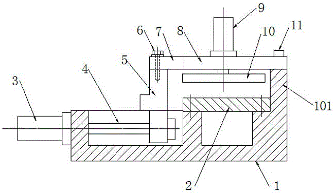
[0010] Such as figure 1 As shown, the sawing fixture with an improved structure includes a fixture body 1 and a movable clamping plate 5. The fixture body 1 is a vise-type body structure. One end of the fixture body is a fixed clamping plate 101. The middle part of the fixture body 1 is provided with a mounting groove. , the movable clamping platen 5 is guided on the fixture body, and the cylinder 3 is installed on the fixture body, and the piston rod of the cylinder 3 is fixedly connected with the bottom of the movable clamping platen 5; A supporting plate 2 fixed on the fixture body is provided between the pressing plates 101;

[0011] A connecting plate 8 is arranged on the fixed clamping platen 101 and the movable clamping platen 5, and one end of the connecting plate 8 is fixedly connected to the fixed clamping platen 101 by a screw 11, and the other end of the connecting plate is provided with a U-shaped slot 7 , the screw and gasket assembly 6 pass through the U-shaped...


PUM


Abstract

The invention provides a sawing machine clamp of an improved structure. The sawing machine clamp comprises a clamp body and a movable clamping pressing plate. The clamp body is of a vice type body structure. A fixed clamping pressing plate is arranged at one end of the clamp body. The movable clamping pressing plate is guided on the clamp body. An air cylinder is mounted on the clamp body and used for pushing the movable clamping pressing plate. A supporting plate is arranged between the movable clamping pressing plate and the fixed clamping pressing plate. A connecting plate is arranged on the fixed clamping pressing plate and the movable clamping pressing plate. A pressing air cylinder is vertically fixed to the connecting plate. A pressing plate is connected to a piston rod of the pressing air cylinder. The sawing machine clamp can clamp round steels in the horizontal and vertical directions and can clamp at least three round steels at a time and is reliable in clamping, at least three parts can be discharged through one time of clamping, and thus the working efficiency is improved; and the pressing air cylinders are used for clamping in the two directions, and pressing is safe and reliable.

Description

technical field [0001] The invention relates to a jig for a sawing machine. Background technique [0002] In order to realize loading and unloading on the sawing machine, manual vise-type clamps are generally used on the sawing machine workbench, which has only one direction of clamping force, and can only clamp one round steel at a time, and the blanking efficiency is low. Contents of the invention [0003] In order to improve the cutting efficiency on the sawing machine and improve the working efficiency, the invention proposes a sawing machine fixture with an improved structure. [0004] In order to achieve the purpose, the present invention adopts the following technical solutions: a sawing fixture with an improved structure, including a fixture body and a movable clamping plate, the fixture body is a vise-type body structure, one end of the fixture body is a fixed clamping plate, and the middle part of the fixture body is set There are installation grooves, and the m...

Claims


Application Information

Patent Timeline
Patent Type & Authority Applications(China)
IPC IPC(8): B23Q3/08
CPCB23Q3/08
Inventor 胡斌潘宇
Owner 湖北衡兴锻造有限公司
Learn More