Novel purse-string forceps for laparoscope
A laparoscopic and purse-string forceps technology is applied in the field of new laparoscopic purse-string forceps, and achieves the effects of convenient suture, convenient operation and convenient use of the purse string.
- Summary
- Abstract
- Description
- Claims
- Application Information
AI Technical Summary
Problems solved by technology
Method used
Image
Examples
Embodiment 1
[0029] Embodiment 1 Novel laparoscopic purse forceps of the present invention
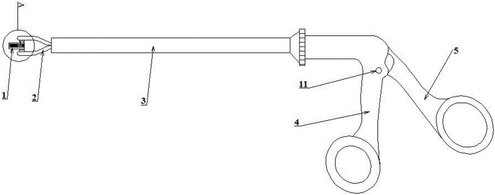
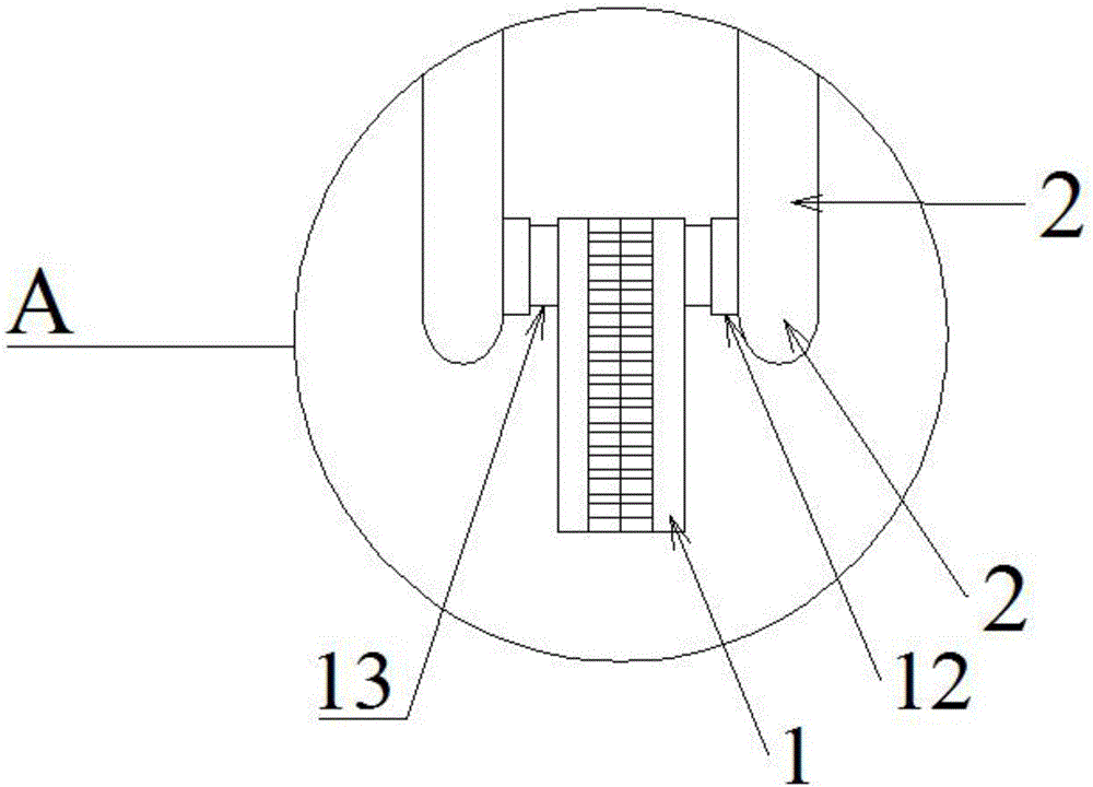
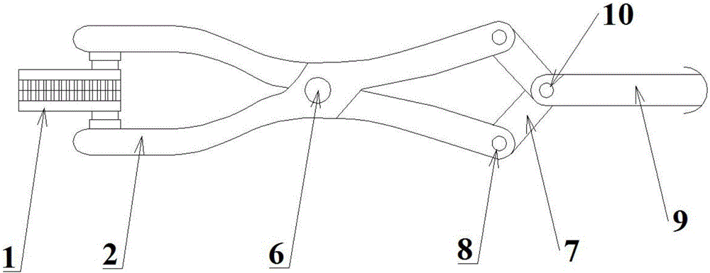
[0030] See Figure 1-Figure 3 . attached figure 1 It is the structural representation of laparoscopic purse forceps of the present invention, appended figure 2 for figure 1 Enlarged schematic diagram of region A in the middle, with image 3 It is a schematic diagram of the connection of the clamp, the handle of the pliers, the connecting rod and the pull rod in the present invention.
[0031] A new type of purse forceps for laparoscopy, comprising a clamp 1, a handle 2, a sleeve 3, a fixed handle 4, a swing handle 5, the handle 2 includes an upper handle and a lower handle, an upper handle and a lower handle The handle is fixed on the head end of the casing 3 through the pin shaft 6, and the upper clamp handle and the lower clamp handle can rotate with each other. The rear end of the clamp handle 2 and the front ends of the two connecting rods 7 pass through two hinge shafts 8 A planar four-...
Embodiment 2
[0033] Embodiment 2 The improvement scheme of the present invention
[0034] The structure of the purse pliers of this embodiment is substantially the same as that of Embodiment 1, the difference is that there is an angle positioning device between the sleeve and the inner sleeve, so that the pliers are clamped at 30° and 60° to the plane where the pliers handle is located. , 90°, 120°, the angle between the clamp and the handle is fixed, which is convenient for intraoperative operation.
[0035] The structure of the sleeve 12 and the inner sleeve 13 and its connection mode are as follows: Figure 4 shown. The sleeve 12 is hollow tubular, and one end of the sleeve 12 is fixed on the surface of the pliers handle 2; a rotating shaft 14 is arranged inside the sleeve 12, and the rotating shaft 14 is arranged at the axial position of the sleeve 12 and fixed with the pliers handle 2 Connection; the rotating shaft 14 is provided with a slope 15 on the two parts close to the pliers ha...
PUM
 Abstract
Description
Claims
Application Information
 - Generate Ideas
- Intellectual Property
- Life Sciences
- Materials
- Tech Scout
- Unparalleled Data Quality
- Higher Quality Content
- 60% Fewer Hallucinations
Browse by: Latest US Patents, China's latest patents, Technical Efficacy Thesaurus, Application Domain, Technology Topic, Popular Technical Reports.
© 2025 PatSnap. All rights reserved.Legal|Privacy policy|Modern Slavery Act Transparency Statement|Sitemap|About US| Contact US: help@patsnap.com


