
Gate drive circuit, gate drive method and display device

A gate drive circuit and gate drive technology, used in static indicators, digital memory information, instruments, etc., can solve the problems of leakage of display memory cells and inability to maintain potential.

Active Publication Date: 2017-05-24
HEFEI BOE OPTOELECTRONICS TECH +1
View PDF9 Cites 10 Cited by
  • Summary
  • Abstract
  • Description
  • Claims
  • Application Information

AI Technical Summary

Problems solved by technology

[0003] The main purpose of the present invention is to provide a gate drive circuit, a gate drive method and a display device, which solve the problem that the potential of the pull-up node cannot be maintained at a high level in the output stage due to the leakage of the display storage unit in the existing gate drive circuit. level, resulting in the problem of no gate drive signal output

Method used


Image

  • Gate drive circuit, gate drive method and display device
  • Gate drive circuit, gate drive method and display device
  • Gate drive circuit, gate drive method and display device

Examples


Embodiment Construction

[0050] The following will clearly and completely describe the technical solutions in the embodiments of the present invention with reference to the accompanying drawings in the embodiments of the present invention. Obviously, the described embodiments are only some, not all, embodiments of the present invention. Based on the embodiments of the present invention, all other embodiments obtained by persons of ordinary skill in the art without making creative efforts belong to the protection scope of the present invention.

[0051] The transistors used in all the embodiments of the present invention can be thin film transistors or field effect transistors or other devices with the same characteristics. In the embodiment of the present invention, in order to distinguish the two poles of the transistor except the gate, one pole is called the first pole, and the other pole is called the second pole. In actual operation, the first electrode may be a drain, and the second electrode may...


PUM


Abstract

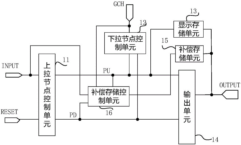
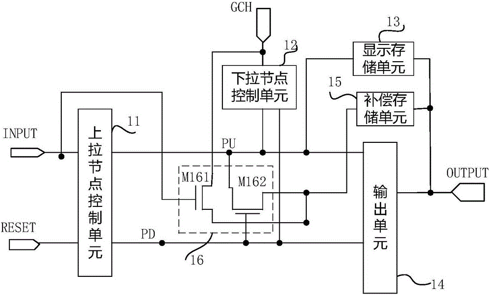
The invention provides a gate drive circuit, a gate drive method and a display device. The gate drive circuit comprises a pull-up node control unit, a pull-down node control unit, a display and storage unit and an output unit. The gate drive circuit also comprises a compensation and storage unit and a compensation and storage control unit. The compensation and storage control unit is connected with an input end, a pull-down control voltage end, a pull-up node, a pull-down node and the second end of the compensation and storage unit and used for controlling the pull-down control voltage end to be connected with the second end of the compensation and storage unit in the input phase under the control of the input end so as to charge the compensation and storage unit and also used for controlling the second end of the compensation and storage unit to be connected with the pull-up node in the output phase when the potential of the pull-down node is high level. The problem that the existing gate drive circuit has no gate drive signal output can be solved by the gate drive circuit, the gate drive method and the display device.

Description

technical field [0001] The present invention relates to the technical field of display driving, in particular to a gate driving circuit, a gate driving method and a display device. Background technique [0002] With the development of display technology, the market has higher and higher requirements for the reliability of display panels. The GOA (Gate On Array, gate drive circuit set on the array substrate) circuit using traditional design methods is also difficult to operate in harsh environments. More and more problems were exposed. For example, under high temperature and high humidity conditions, the characteristics of the TFT (Thin Film Transistor, thin film transistor) device included in the GOA circuit will change, and the off-state leakage current of the TFT device will increase significantly, which will directly cause the memory cell to be displayed during the gate drive signal output stage. Leakage leads to deterioration of power retention characteristics, so that ...

Claims


Application Information

Patent Timeline
Patent Type & Authority Applications(China)
IPC IPC(8): G09G3/20
CPCG09G3/20G11C19/28G09G2310/0267G09G2310/0289G09G2300/0408G09G2310/08G09G2330/023G09G3/2092G09G2300/043G09G2310/0286G09G3/3677
Inventor 廖力勍李红敏宋萍
Owner HEFEI BOE OPTOELECTRONICS TECH
Learn More