
Self-calibrating type biochemical reaction tank

A biochemical reaction and self-calibration technology, applied in the direction of material electrochemical variables, etc., can solve the problems of small reaction contact surface, low reaction point alignment, slow reaction speed, etc., to avoid cross contamination.

Inactive Publication Date: 2017-05-24
重庆市锋致科技有限责任公司
View PDF0 Cites 0 Cited by
  • Summary
  • Abstract
  • Description
  • Claims
  • Application Information

AI Technical Summary

Problems solved by technology

[0003] The purpose of the present invention is to overcome the shortcomings and deficiencies of the above-mentioned prior art, provide a self-calibrating biochemical reaction cell, and solve the problem that the alignment of the hole of the spacer in the biochemical reaction cell of the existing electrochemical biochip and the reaction point on the chip is not high, resulting in The reaction interface is small and the reaction speed is slow

Method used


Image

  • Self-calibrating type biochemical reaction tank
  • Self-calibrating type biochemical reaction tank
  • Self-calibrating type biochemical reaction tank

Examples


Embodiment 1

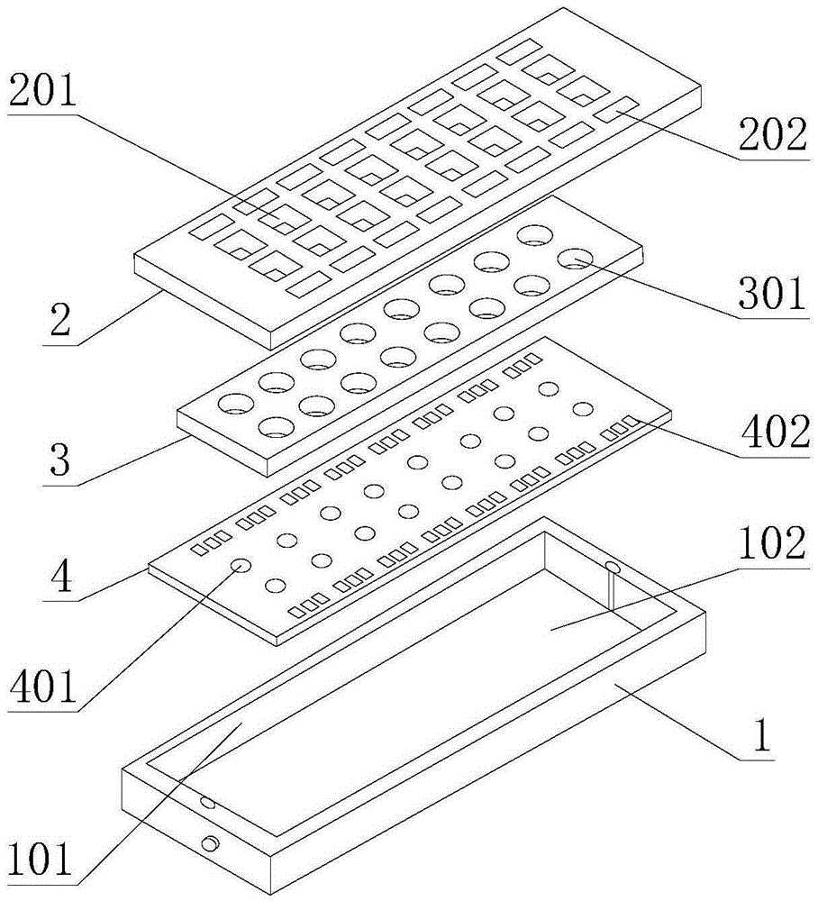
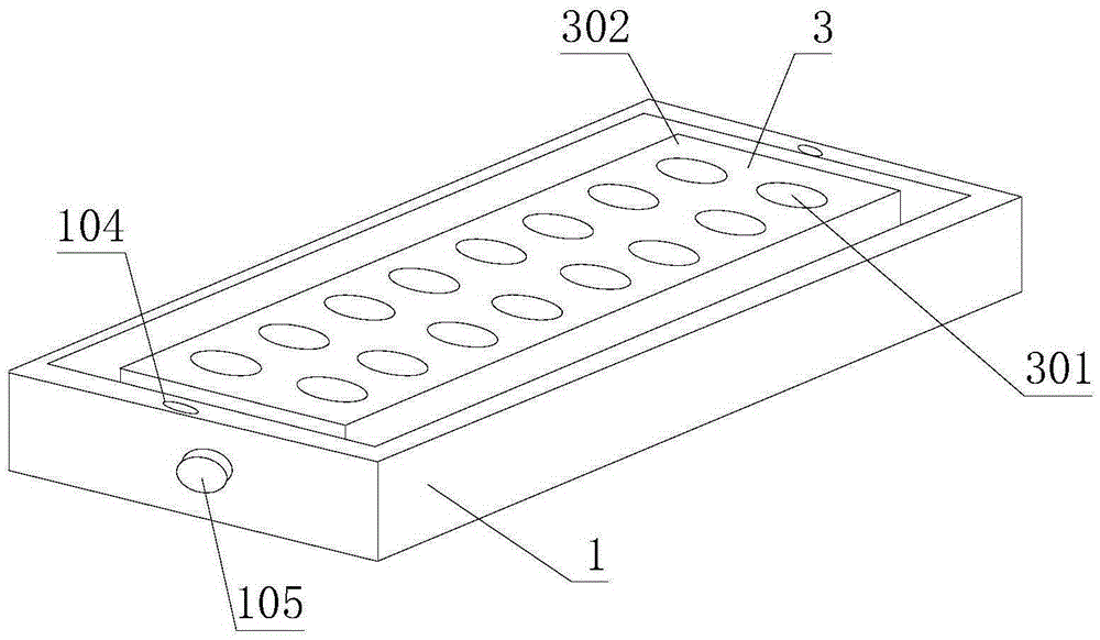
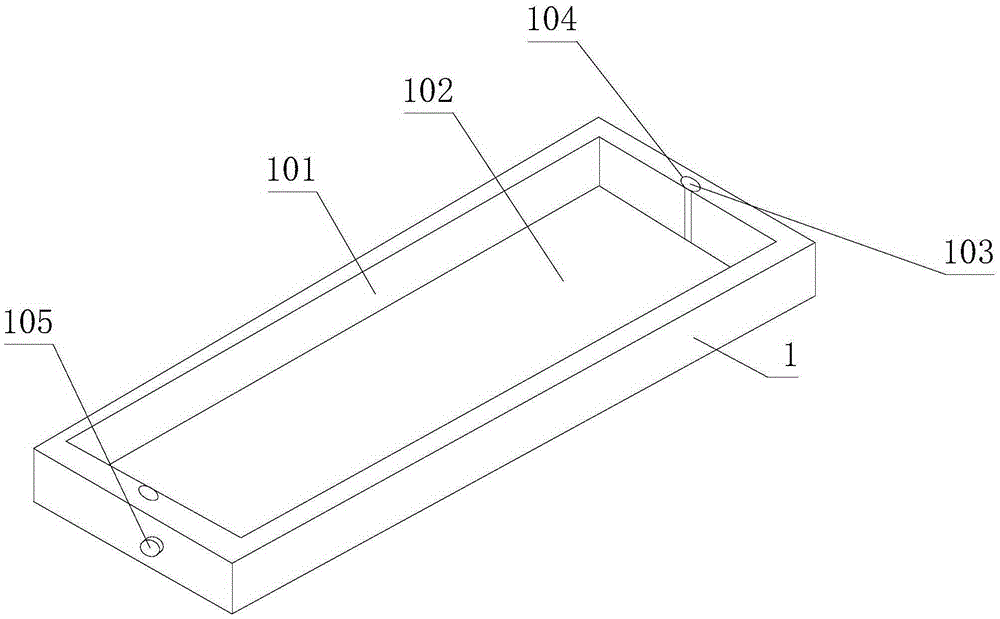
[0024] Such as Figure 1 to Figure 6 As shown, the self-calibrating biochemical reaction pool includes a bottom box 1 and a spacer 3. The bottom box 1 is provided with a chip groove 101, and an upper cover 2 is arranged at the notch of the chip groove 101. Cover 2 can seal the notch of chip groove 101, spacer 3 can be put in the chip groove 101, is provided with a plurality of reaction pools 301 on it, and reaction pool 301 is the hole that runs through spacer 3, and upper cover 2 A plurality of liquid inlet windows 201 and a plurality of electrical connection windows 202 are provided, and the liquid inlet windows 201 correspond to the reaction pools 301 one by one, and a lifting plate 102 is arranged at the bottom of the chip groove 101, and the size of the lifting plate 102 is the same as The chip groove 101 cooperates, and the two corresponding side ends of the lifting plate 102 are all provided with a bar-shaped toothed bar 103, the bar-shaped toothed bar 103 is perpendicu...

Embodiment 2

[0031] Such as Figure 7 to Figure 9 As shown, the structure of this embodiment is basically the same as that of Embodiment 1, the difference is that one side of the upper cover 2 is hinged to the bottom box 1, and a buckle 203 is provided on the opposite side of the side, and a buckle 203 is arranged on the buckle 203 There is a spring piece 204 protruding in an arc shape, and a buckle groove 108 is provided at a position corresponding to the buckle 203 on the bottom box 1 . The upper cover 2 of the device is hinged with the bottom box 1, that is, the upper cover 2 is flipped open and closed, and the other side is a buckle 203. When the upper cover 2 needs to be fixed, the buckle 203 is inserted into the buckle groove 108, and the buckle 203 And the size of the spring sheet 204 is slightly larger than the buckle groove 108, so that the buckle 203 can be pressed into the buckle groove 108 after the spring sheet 204 shrinks. Because the spring sheet 204 presses the buckle groov...


PUM


Abstract

The invention discloses a self-calibrating type biochemical reaction tank which comprises a bottom box (1) and a partition (3), wherein a chip groove (101) is formed in the bottom box (1); an upper cover (2) is arranged in a slot opening of the chip groove (101); a lifting plate (102) is arranged on the bottom of the chip groove (101); a square slot (302) is formed in each of four corners of the upper end surface of the partition (3); and matched semicircular bulges (205) are arranged on positions, which correspond to semicircular slots (302), of the upper cover (2). The self-calibrating type biochemical reaction tank has the beneficial effects that: the square slots are formed in the partition, and the semicircular bulges are arranged on the upper cover, so that the partition is precisely positioned after the semicircular bulges enter the square slots; and moreover, slot depth is smaller than the radius of the partition, and the partition is elastically pressed by the semicircular bulges made of rubber, so that the partition tightly fits with a chip.

Description

technical field [0001] The invention relates to the field of biochemical reactions, in particular to a self-calibrating biochemical reaction pool. Background technique [0002] Electrochemical biochips can be widely used in various sectors of the national economy such as food, pharmaceuticals, chemicals, clinical testing, biomedicine, and environmental monitoring due to their fast, accurate, and highly sensitive characteristics. Electrochemical biochips need to add corresponding detection reagents to the reaction unit when detecting samples. Without the protection of an effective anti-liquid diffusion device, the detection samples on each reaction unit will often diffuse under the action of liquid reagents, resulting in Cross-contamination between different samples leads to a decrease in the sensitivity and accuracy of the test results, or even failure to detect, which brings great inconvenience to users, and also causes a waste of precious reagents and scarce sample resourc...

Claims


Application Information

Patent Timeline
Patent Type & Authority Applications(China)
IPC IPC(8): G01N27/26
CPCG01N27/26
Inventor 傅严锋
Owner 重庆市锋致科技有限责任公司
Learn More