Phase imaging device and method based on dark stripe logic judgment
A technology of logical judgment and imaging equipment, applied in the direction of instruments, measuring devices, scientific instruments, etc., can solve the problems of multiple measurements, sensitivity to noise, poor phase resolution, etc.
- Summary
- Abstract
- Description
- Claims
- Application Information
AI Technical Summary
Problems solved by technology
Method used
Image
Examples
Embodiment 1
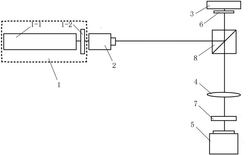
[0109] refer to figure 1 , the first embodiment of the present invention provides a phase imaging device based on dark fringe logic judgment. The phase imaging device includes: a light source device 1 , a beam expander and collimator element 2 , a spatial light modulator 3 , a lens element 4 , an array detector 5 and an image generating device (not shown in the figure).
[0110] The connection relationship and working process of each component of the temperature measuring equipment can be described as follows:
[0111] The light source device 1 emits polarized laser light toward the object to be measured 6 , and the polarized laser beam is expanded by the beam expander and collimation element 2 , so that the beam spot size is adapted to the size of the object to be measured 6 and the modulation area of the spatial light modulator 3 . The polarized laser light penetrates the object to be measured 6 and arrives at the spatial light modulator 3. The spatial light modulator 3 p...
specific example
[0129] Assuming that the actual pixels of the object 6 to be tested are 16×16, its actual image is expressed in a matrix as:
[0130]
[0131] and suppose q j There are four values (ie m=4), and because q j can be real and imaginary, so let’s assume that q j =i,-i,-1,1.
[0132] According to the phase value q j The number and value of the four 1×16 matrices are constructed, the pixels in the first column of the matrix are set as the reference pixel r=1, and the ratio between adjacent pixels is Right now:
[0133] f 1 =[1 -i -1 i 1 -i -1 i 1 -i -1 i 1 -i -1 i];
[0134] f 2 =[1 i -1 -i 1 i -1 -i 1 i -1 -i -1 -i 1 i];
[0135] f 3 =[1 -1 1 -1 1 -1 1 -1 1 -1 1 -1 1 -1 1 -1];
[0136] f 4 =[1 1 1 1 1 1 1 1 1 1 1 1 1 1 1 1];
[0137] in the matrix f 1 In , there is a phase ratio between pixels in two adjacent columns in the matrix f 2 In , there is a phase ratio between pixels in two adjacent columns in the matrix f 3 In , there is a phase ratio between pix...
specific example
[0151] still assume q j =i,-i,-1,1, first establish a 4×1 object reference value matrix r for the object to be measured obj ,but Expand it to a 4×4 matrix
[0152] Also set a 1×4 phase mask reference ratio matrix for the phase mask: r pattern = [-i i -1 1];
[0153] the matrix r pattern Extended to a 4×4 matrix
[0154] The above matrix R obj and matrix R pattern Dot multiplication (corresponding element multiplication) to get the dot product matrix B:
[0155]
[0156] When the element in the dot product matrix B is 1, the position is replaced with 0, when the element in the dot product matrix B is not 1, the position remains unchanged and is still recorded as 1, thus obtaining a combination of 0 and 1 Form a reference library matrix of size m×m
[0157] In particular, if r obj with r pattern When the corresponding elements are arranged in positive order, R is a matrix whose positive diagonal elements are 0 and the rest of the position elements are 1; if ...
PUM
 Abstract
Description
Claims
Application Information
 - R&D
- Intellectual Property
- Life Sciences
- Materials
- Tech Scout
- Unparalleled Data Quality
- Higher Quality Content
- 60% Fewer Hallucinations
Browse by: Latest US Patents, China's latest patents, Technical Efficacy Thesaurus, Application Domain, Technology Topic, Popular Technical Reports.
© 2025 PatSnap. All rights reserved.Legal|Privacy policy|Modern Slavery Act Transparency Statement|Sitemap|About US| Contact US: help@patsnap.com


