
A high-precision infrared imaging system image plane interface method

An infrared imaging system and high-precision technology, applied in the field of through-the-center and image-to-surface contact, can solve the problem that the optical axis of the optical lens and the center normal of the focal plane target surface cannot be guaranteed, and achieve good imaging effect, through-center The effect of high precision and easy operation

Active Publication Date: 2017-12-26
西安中科飞图光电科技有限公司
View PDF6 Cites 0 Cited by
  • Summary
  • Abstract
  • Description
  • Claims
  • Application Information

AI Technical Summary

Problems solved by technology

[0003] In order to solve the technical problem that the coincidence accuracy of the optical axis of the optical lens and the normal line of the center of the target surface of the focal plane cannot be guaranteed in the process of passing through the existing infrared optical lens and the infrared imaging focal plane, the present invention provides a high-precision infrared imaging system image Face-to-face device and method

Method used


Image

  • A high-precision infrared imaging system image plane interface method
  • A high-precision infrared imaging system image plane interface method
  • A high-precision infrared imaging system image plane interface method

Examples


Embodiment Construction

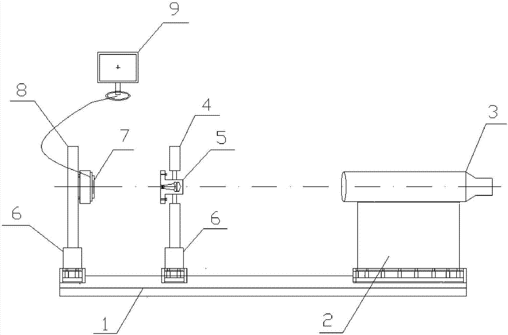
[0032] see figure 1 , the present invention provides a high-precision infrared imaging system image plane docking device, the structure of its preferred embodiment includes a display 9 and an optical rail 1 arranged horizontally, and an infrared image detector 7, an infrared optical Imaging lens 5 and collimator 3.

[0033] Wherein, the infrared image detector 7 is installed on the detector bracket 8 first, and then connected to the optical guide rail 1 through the combined moving platform 6; the focal plane of the infrared image detector 7 faces the infrared optical imaging lens 5. The infrared image detector 7 is connected to the display 9, and the display in this embodiment is a self-generating electric cross-hair display in the center of the display area.

[0034] The infrared optical imaging lens 5 is installed on the lens holder 4 first, and then connected with the optical rail 1 through the combined moving platform 6 .

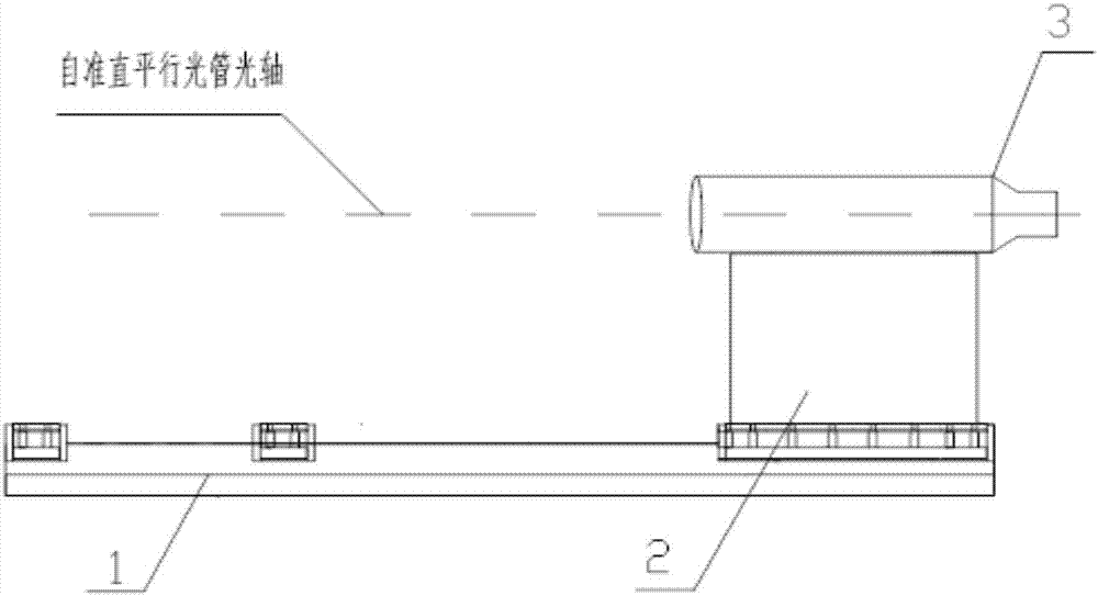
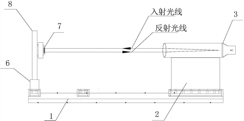
[0035] The collimator 3 is connected with the o...


PUM


Abstract

The invention relates to a high-precision infrared imaging system imaging plane docking device and method which are applied to the imaging plane docking and centering of infrared optical imaging systems in the aviation and aerospace field. The device comprises a display and a horizontally-arranged optical guide rail; the optical guide rail is sequentially provided with an image detector, an infrared optical imaging lens and a parallel optical tube; the image detector is connected with the optical guide rail through a combined mobile station; the image detector comprises an image detector focal plane which faces an infrared optical imaging lens; the image detector is connected with the display; the infrared optical imaging lens is connected with the optical guide rail through a combined mobile station; the parallel optical tube is connected with the optical guide rail through a parallel optical tube support; and the parallel optical tube support and the combined mobile stations can perform three-dimensional translation and rotation. The infrared imaging system centering device of the invention has the advantages of simple structure and convenient operation, and can be widely applied to engineering practice, especially mass production scientific research tasks.

Description

technical field [0001] The invention relates to a high-precision infrared imaging system image plane docking device and method, which are applied to the image plane docking and penetration of infrared optical imaging systems in the fields of aviation and aerospace. Background technique [0002] The infrared imaging camera composed of the infrared optical imaging system and the infrared imaging focal plane is an important component of the aircraft in the aerospace and aviation fields. It provides video images for various tasks and facilitates ground monitoring and control. Infrared optical imaging systems have very high requirements on the coincidence accuracy of the optical axis of the optical system and the center normal of the imaging focal plane target surface. How to ensure the above-mentioned index requirements during the assembly process of infrared imaging equipment becomes the key to determining the imaging quality and measurement accuracy of infrared imaging equipmen...

Claims


Application Information

Patent Timeline
Patent Type & Authority Patents(China)
IPC IPC(8): G01J5/02G01J5/08G01J5/00
CPCG01J5/00G01J5/0205G01J5/0806G01J2005/0077
Inventor 武力曹剑中刘伟淡佳伟屈波杨凯党艳玲何月娜
Owner 西安中科飞图光电科技有限公司
Learn More