
Non-stop air compressor

A technology of air compressor and main engine, applied in the direction of machine/engine, mechanical equipment, liquid fuel engine, etc., can solve the problems of large load shock, delayed production, switching voltage drop, etc.

Active Publication Date: 2017-05-24
SAZHEN COMPRESSOR SHANGHAI CO LTD
View PDF6 Cites 2 Cited by
  • Summary
  • Abstract
  • Description
  • Claims
  • Application Information

AI Technical Summary

Problems solved by technology

[0003] Existing air compressors have a maintenance cycle, and at least half a day of production needs to be wasted during maintenance; once a failure occurs, no matter what the failure is, the manufacturer needs to repair it, and the time is uncertain, delaying production; the electrical control system is the point of failure, once it occurs If there is a fault, it cannot be used; the air filter should be purged regularly, otherwise the efficiency will decrease, and the production will be delayed when purging
[0004] Some industries use air compressors to run 24 hours a day, and basically cannot be shut down throughout the year. Shutdown will affect production, equipment failure, maintenance, and maintenance. Shutdown is required, and the failures are mostly electrical failures, oil separation failures and high temperature failures. , the real main engine motor failure is rare, but downtime will affect production, adding a spare machine will increase too much cost, and most users are not willing to increase this cost, so it is necessary to make a machine that does not need downtime Air compressor, to solve such problems
[0005] The traditional ordinary frequency converter has the following defects: large impact on the load, large damage, switching voltage drop, unstable, type selection requires power several times larger than the load, and high cost. For some lighting loads with phase requirements (such as sodium lamps) ,can not be used

Method used


Image

  • Non-stop air compressor
  • Non-stop air compressor
  • Non-stop air compressor

Examples


Embodiment 1

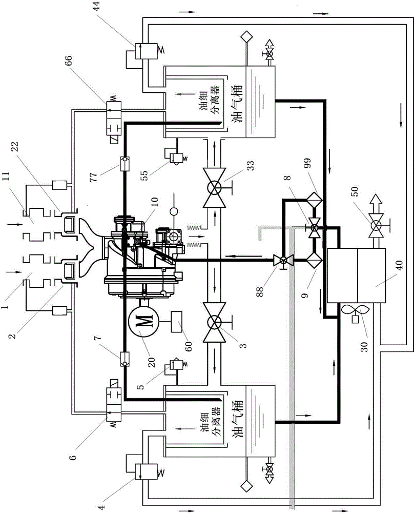
[0034] like figure 1 As shown, a non-stop air compressor of the present invention is a twin-screw air compressor, which includes a main engine 10, two sets of air intake systems, two sets of oil-gas separation systems, and two sets of oil-gas separation systems sharing an oil-gas cooler. Cooling system; each air intake system includes an air filter (1) 1, an air filter (2) 11, an air intake valve (1) 2, an air intake valve ( 2) 22; each set of oil-gas separation system includes an oil-gas barrel with an oil-fine separator connected to the main engine. ) 33), a pressure maintaining valve connected to the oil-gas cooler (i.e. pressure maintaining valve (1) 4, pressure maintaining valve (2) 44), a safety valve (i.e. safety valve (1) 5, safety valve (2) 55), a discharge solenoid valve set on the top of the oil and gas barrel (ie discharge solenoid valve (1) 6, discharge solenoid valve (2) 66), an oil return sheet set between the oil fine separator and the main engine Directional...


PUM


Abstract

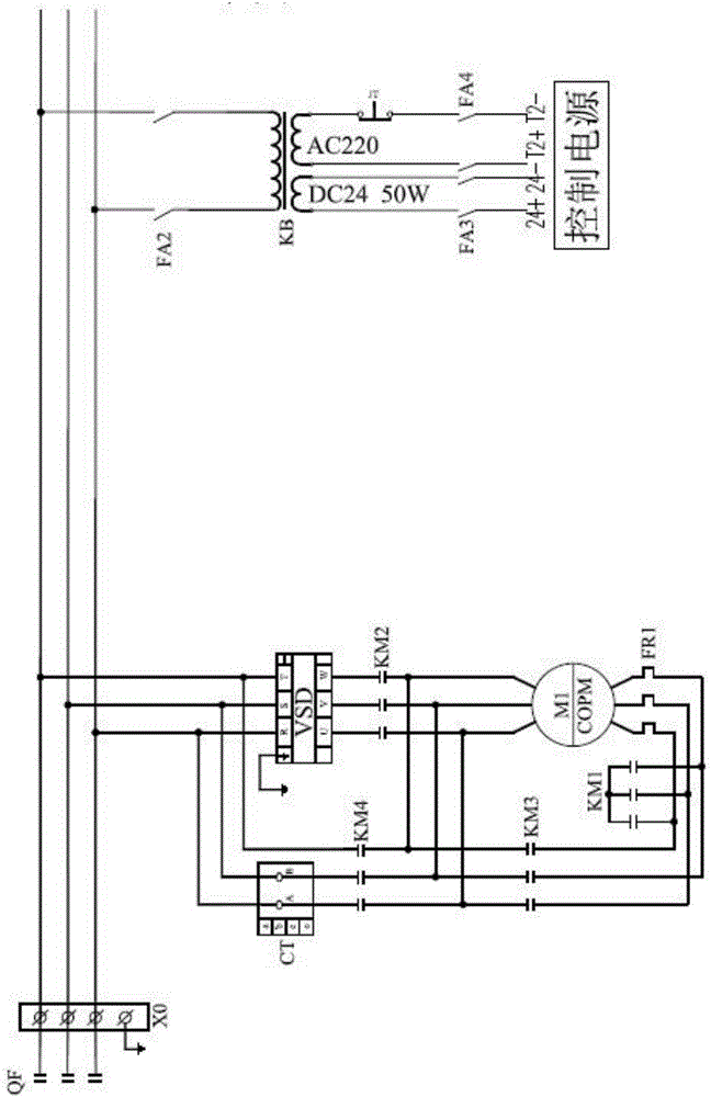
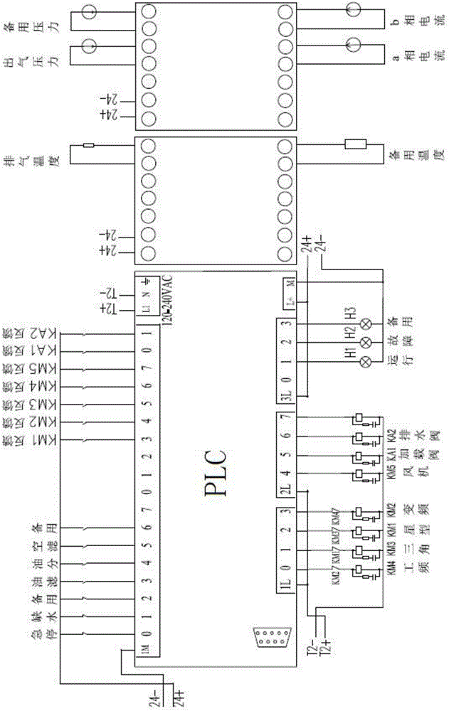
The invention discloses a non-stop air compressor. The non-stop air compressor comprises a main compressor, two sets of air inlet systems, two sets of oil-air separation systems and two sets of oil-air cooling systems sharing an oil-air cooler. The non-stop air compressor is provided with a power frequency and frequency conversion dual-control system. A main motor achieves star connection through a first contactor and achieves triangular connection through a third contactor. Starting of the air compressor is star-triangular switching starting. The main motor is connected with the output end of a frequency converter through a second contactor. The input end of the frequency converter is connected to a three-phase power source. The main motor is connected to the three-phase power source through a fourth contactor. The input end of a control power source is connected to the three-phase power source through a transformer. Due to the facts that the non-stop air compressor is provided with two sets of systems (double oil filters, double oil-air barrel systems and the double air inlet systems) and the power frequency and frequency conversion dual-control system is adopted, when one set of systems is in fault or needs maintenance, operation can be switched to the other set of systems, and thus normal operation of the air compressor is ensured.

Description

technical field [0001] The invention belongs to the technical field of lubricating equipment, and relates to a non-stop air compressor. Background technique [0002] Air compressor is an essential infrastructure in industrial production. The stability of air compressor operation directly affects the sustainability of production and the stability of product quality. Especially for high-speed machining, constant pressure supply is very important. [0003] Existing air compressors have a maintenance cycle, and at least half a day of production needs to be wasted during maintenance; once a failure occurs, no matter what the failure is, the manufacturer needs to repair it, and the time is uncertain, delaying production; the electrical control system is the point of failure, once it occurs If there is a fault, it cannot be used; the air filter must be purged regularly, and the efficiency will decrease if it is not purged, and the production will be delayed when purging. [0004]...

Claims


Application Information

Patent Timeline
IPC IPC(8): F04C23/02F04C28/28F04C29/02F04C29/04
CPCF04C23/02F04C28/28F04C29/026F04C29/04
Inventor 张清源丁刚程红星廖铁强吴金勇
Owner SAZHEN COMPRESSOR SHANGHAI CO LTD
Learn More