
Device for improving Rankine cycle heat efficiency

A Rankine cycle and thermal efficiency technology, applied in steam engine devices, machines/engines, mechanical equipment, etc., can solve the problems of reducing the thermal efficiency of the Rankine cycle and losing the heat energy of exhausted steam

Inactive Publication Date: 2017-05-24
WUXI XUELANG ENVIRONMENTAL TECH CO LTD
View PDF7 Cites 0 Cited by
  • Summary
  • Abstract
  • Description
  • Claims
  • Application Information

AI Technical Summary

Problems solved by technology

[0002] The steam power cycle of the steam engine and steam turbine that converts steam heat energy into mechanical energy, the state change process of its working medium is carried out according to the Rankine cycle, in which the Rankine cycle is mainly composed of boilers, steam turbines, generators, condensers and feed water pumps , the steam coming out of the boiler enters the steam turbine through the pipeline, and part of the heat energy of the steam is converted into mechanical energy to drive the generator to generate electricity. The water is sent back to the boiler by the feed water pump. So far, the working medium has completed a closed process, that is, the Rankine cycle. However, during this cycle, the low-pressure exhaust steam that has done work releases heat to the outside, and almost all of the exhaust steam is lost. All heat energy reduces the thermal efficiency of the Rankine cycle

Method used


Image

  • Device for improving Rankine cycle heat efficiency

Examples


Embodiment Construction

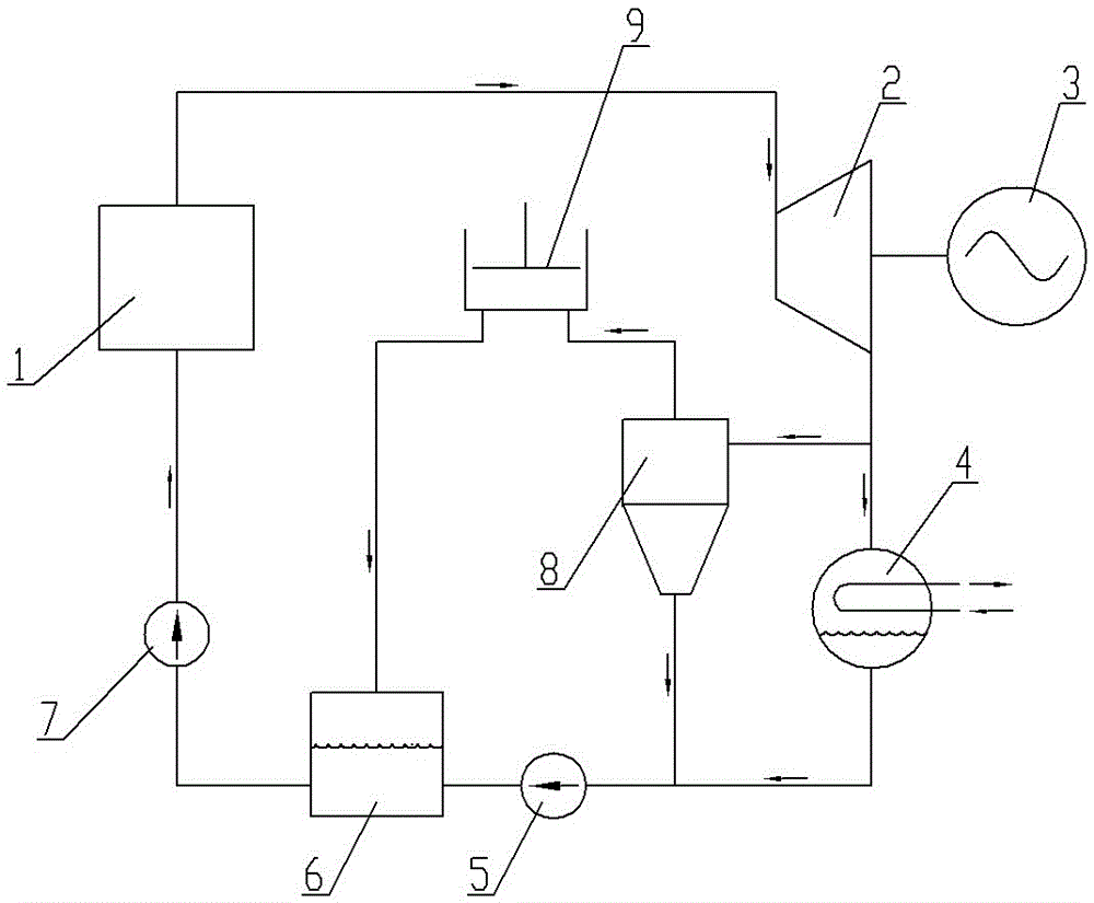
[0007] Such as figure 1 As shown, the present invention comprises a boiler 1, a steam turbine 2, a generator 3, a condenser 4, a circulation pump 5, a mixing tank 6, a feed water pump 7, a vapor-liquid separator 8, and a pressurizer 9, wherein the boiler 1 is an energy Conversion equipment, input energy to heat liquid to generate steam; steam turbine 2 is a device that converts steam heat energy into mechanical energy and drives generator 3 to generate electricity; condenser 4 is a cooling device for exhaust steam, and the exhaust steam is cooled into liquid under the action of cooling medium; Circulation pump 5 provides power for working medium circulation; mixing water tank 6 liquid heating and storage equipment, mixed with steam to directly heat liquid; feed water pump 7 provides power for working medium circulation; vapor-liquid separator 8 plays the role of steam and liquid separation; pressurizer 9 is steam boosting and heating equipment; the inlet of boiler 1 is connect...


PUM


Abstract

The invention provides a device for improving Rankine cycle heat efficiency, which can recover one part of waste steam and effectively uses heat energy of the waste steam to reduce external heat input to save the energy so as to reduce the heat energy loss of the waste steam and to improve the Rankine cycle heat efficiency. The device comprises a boiler, a steam turbine, a generator, a steam condenser, a water feeding pump, a circulating pump, a mixed water tank, a steam-liquid separator and a press; an inlet of the boiler is connected with an outlet of the water feeding pump; an outlet of the boiler is connected with an inlet of the steam turbine; an outlet of the steam turbine is connected with inlets of the steam-liquid separator and the steam condenser; the steam turbine is connected with the generator; an outlet of the steam condenser is connected with an inlet of the circulating pump and an outlet of the steam-liquid separator; an outlet of the circulating pump is connected with a liquid inlet on one corresponding side of the mixed water tank; a steam inlet of the mixed water tank is connected with an outlet of the press; a liquid outlet on the other side of the mixed water tank is connected with an inlet of the water feeding pump; a steam outlet of the steam-liquid separator is connected with an inlet of the press; and cooling medium inlet and outlet of the steam condenser are respectively connected with a cold source.

Description

technical field [0001] The invention relates to the technical field of heat treatment and equipment, in particular to a device for improving the thermal efficiency of a Rankine cycle. Background technique [0002] The steam power cycle of the steam engine and steam turbine that converts steam heat energy into mechanical energy, the state change process of its working medium is carried out according to the Rankine cycle, in which the Rankine cycle is mainly composed of boilers, steam turbines, generators, condensers and feed water pumps , the steam coming out of the boiler enters the steam turbine through the pipeline, and part of the heat energy of the steam is converted into mechanical energy to drive the generator to generate electricity. The water is sent back to the boiler by the feed water pump. So far, the working medium has completed a closed process, that is, the Rankine cycle. However, during this cycle, the low-pressure exhaust steam that has done work releases hea...

Claims


Application Information

Patent Timeline
IPC IPC(8): F01K17/02F01K13/00F01D15/10
CPCF01K17/025F01D15/10F01K13/006
Inventor 尹华勤
Owner WUXI XUELANG ENVIRONMENTAL TECH CO LTD
Learn More