
Mortise lock

A technology for mortise locks and deadbolts, which is applied to building locks, non-mechanical transmission-operated locks, buildings, etc. It can solve problems such as unfavorable intelligent monitoring, cumbersome operation, and complex structure, and achieve improved product appearance and simplified operation steps. , the effect of small shape restrictions

Active Publication Date: 2017-05-24
HANGZHOU YIXINAN IND
View PDF5 Cites 8 Cited by
  • Summary
  • Abstract
  • Description
  • Claims
  • Application Information

AI Technical Summary

Problems solved by technology

The existing electronic mortise lock mainly opens and closes the clutch through the motor, and then manually opens and closes the deadbolt. The operation is cumbersome, the noise is large, and it is not conducive to intelligent monitoring, and because the clutch is installed, the structure is complicated, and the shape is greatly restricted.

Method used


Image

  • Mortise lock
  • Mortise lock
  • Mortise lock

Examples


Embodiment 1

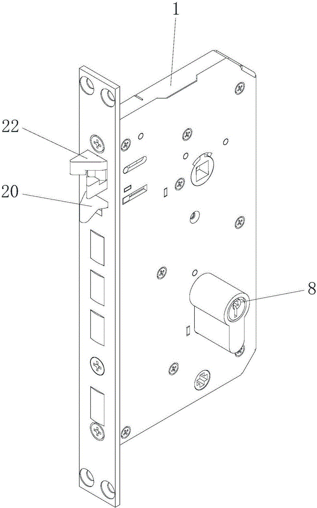
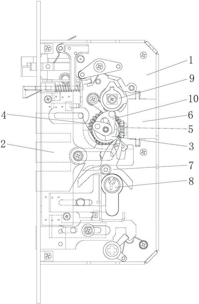
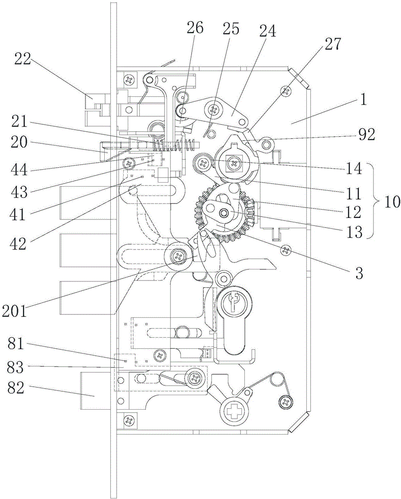
[0036] Please refer to figure 1 -, figure 2 and Figure 8 As shown, the present invention provides a mortice lock, comprising: a housing 1, a main deadbolt 2, a deadbolt rotary block 3, a first bevel gear 4, a second bevel gear 5, a motor 6, a key pick 7 and a lock Core 8.

[0037] The main lock tongue 2 is slidably disposed in the housing 1 . One end of the lock tongue rotating block 3 is rotatably arranged in the housing 1 , and the other end cooperates with the main lock tongue 2 to push the main lock tongue 2 to slide. The first bevel gear 4 is rotatably arranged in the housing 1 . The first bevel gear 4 has a pushing portion 401 cooperating with the deadbolt rotary block 3 for pushing the deadbolt rotary block 3 to rotate. The second bevel gear 5 meshes with the first bevel gear 4 . The motor 6 is connected to the second bevel gear 5 to drive the second bevel gear 5 to rotate. The key pick piece 7 is rotatably arranged in the housing 1 , and the key pick piece 7 i...

Embodiment 2

[0056] Please refer to Figure 14-17 As shown, the difference between the present embodiment and the first embodiment is that the structures of the handle turning block 9 and the bolt turning block 3 are different from the first embodiment. In this embodiment, the handle turning block 9 directly cooperates with the lock bolt turning block 3 to drive the lock bolt turning block 3 to rotate without transmission through the transmission member 10 . The handle turning block 9 has a hook portion 93, and the dead bolt turning block 3 has an elongated portion 33, and the hook portion 93 cooperates with the elongating portion 33 to control the rotation of the dead bolt turning block 3, that is, the hook The rotation of the part 93 can control the rotation of the deadbolt turning block 3 to pull the main deadbolt 2 back into the housing 1 .

[0057] The handle turning block 9 has a door outer rotating part and a door inner rotating part, the door outer rotating part is used for connec...


PUM


Abstract

The invention provides a mortise lock which comprises a shell, a main spring bolt, a spring bolt rotary block, a first bevel gear, a second bevel gear, a motor, a key picking piece and a lock cylinder. The main spring bolt is arranged inside the shell in a sliding mode; one end of the spring bolt rotary block is rotationally arranged inside the shell, and the other end of the spring bolt rotary block is matched with the main spring bolt to push the main spring bolt to slide; the first bevel gear is arranged inside the shell in a sliding mode, provided with a pushing portion matched with the spring bolt rotary block and used for pushing the spring bolt rotary block to rotate; the second bevel gear is engaged with the first bevel gear; the motor is connected with the second bevel gear to drive the second bevel gear to rotate; the key picking piece is rotationally arranged inside the shell and in sliding connection with the spring bolt rotary block; and the lock cylinder is provided with a rotary movable portion and used for controlling the key picking piece to rotate. According to the mortise lock, the main spring bolt can be directly opened and closed through the motor to achieve unlocking or locking, a clutch is not used, the main spring bolt is not manually opened or closed, the unlocking and locking operation steps are simplified, noise is lowered, and intelligent monitoring is facilitated.

Description

technical field [0001] The invention relates to the technical field of door locks, in particular to a mortise lock. Background technique [0002] The mortise lock is also called the mortise door lock. It is generally composed of a handle, a lock cylinder and a lock body. It is mostly installed on indoor suit doors and security doors. It is one of the most common locks on the market. The existing electronic mortise lock mainly opens and closes the clutch through the motor, and then manually opens and closes the deadbolt. The operation is cumbersome, the noise is large, and it is not conducive to intelligent monitoring, and because the clutch is installed, the structure is complicated, and the shape is greatly restricted. Contents of the invention [0003] The object of the present invention is to solve the above problems and provide a mortice lock, which reduces clutch components, simplifies structure, simplifies operation, and is more conducive to intelligent control. [...

Claims


Application Information

Patent Timeline
IPC IPC(8): E05B47/02E05B63/14E05B3/00
CPCE05B3/00E05B47/0012E05B47/026E05B63/146E05B2047/002E05B2047/0086
Inventor 李红伟
Owner HANGZHOU YIXINAN IND
Learn More