
Method for casting annular thin-wall castings by means of feeding stack box of gating system

A pouring system and stacked box casting technology, which is applied in casting molding equipment, molds, mold components, etc., can solve the problems of difficult material hardness at the cold iron, large differences in pouring temperature, wrong machining allowance, etc., to achieve the appearance of The effect of good quality, high yield, improving production efficiency and product qualification rate

Active Publication Date: 2017-05-24
JIANGSU FAW FOUNDRY
View PDF8 Cites 4 Cited by
  • Summary
  • Abstract
  • Description
  • Claims
  • Application Information

AI Technical Summary

Problems solved by technology

The traditional casting production process of annular thin-walled parts uses a large amount of chilled iron to reduce the shrinkage of the casting. Generally, one box is made flat, but the large amount of chilled iron is easy to produce cold barriers, pores, sand and mud, and chilled iron gaps. Various defects such as shrinkage porosity and high hardness of cold iron materials are difficult to process. The production efficiency is low, the scrap rate is high, and heat treatment is often required, which is costly and easy to deform; It is difficult to effectively solve the shrinkage and porosity. Generally, a large amount of cold iron is used, and defects such as wrong toilet and uneven machining allowance are caused by parting and drafting slope.
Due to the cooling of the molten iron when the ladle is moved in the traditional process, only 2 or 3 castings can be poured in a ladle of molten iron, and the casting temperature of each casting varies greatly, resulting in low production efficiency and high scrap rate

Method used


Image

  • Method for casting annular thin-wall castings by means of feeding stack box of gating system
  • Method for casting annular thin-wall castings by means of feeding stack box of gating system

Examples


Embodiment Construction

[0033] The specific embodiments of the present invention will be further described below in conjunction with the accompanying drawings.

[0034] A casting process method for filling a shrink stack bearing cap with a gating system, specifically includes the following steps:

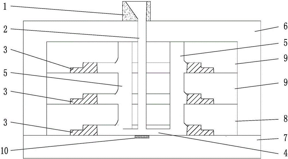
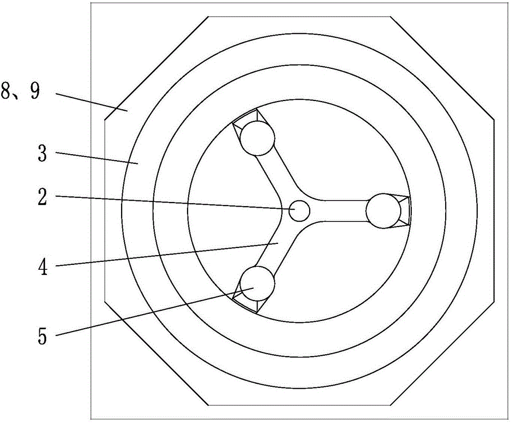
[0035] In the operation process of the present invention, taking casting bearing caps as an example, specifically three bearing caps in a box with a diameter of 1000mm are used for casting, such as figure 1 As shown, the feeding runners 5 are evenly distributed in three equal parts along the circumferential direction of the casting. Generally, three feeding runners are arranged in equal parts within a diameter of 1500mm. However, the diameter of the bearing cap widely used in the market is within 1500mm, so three Feeding runners can meet the purpose of effective feeding, and for special-diameter annular thin-walled parts, the larger the diameter of the casting, the more feeding runners need to be set.

[...


PUM


Abstract

The invention relates to a method for casting castings, in particular to a method for casting annular thin-wall castings by means of a feeding stack box of a gating system. The method is characterized in that firstly, a mould is designed and manufactured; secondly, a core box containing a detachable cross pouring gate, a detachable feeding pouring gate and a casting mould is manufactured; thirdly, a corresponding lower-form and shrinkproof loam core is manufactured, and the loam core and the feeding pouring gate are manufactured according to the number of the castings; fourthly, the mould is matched, and castings are obtained by pouring molten iron after the mould is matched; and fifthly, the qualified castings are obtained after grinding, cleaning and detecting are completed. According to the pouring method of the annular thin-wall castings, the mould is easy to manufacture, a plurality of parts can be manufactured through one box according to needs, the number of the castings through the box can be flexibly adjusted according to needs, the finally formed castings are good in structure and performance, the probability of the shrinking defect is obviously lowered, the cost is low, and the percent of pass of the products is high.

Description

technical field [0001] The invention relates to the field of casting, in particular to a process method for casting an annular thin-walled casting by using a gating system feeding shrink box. Background technique [0002] With the development of the economy, foundry enterprises have higher and higher requirements on the production cost, production efficiency and reject rate of castings, and customers have more and more stringent requirements on product quality. The traditional casting production process of annular thin-walled parts uses a large amount of chilled iron to reduce the shrinkage of the casting. Generally, one box is made flat, but the large amount of chilled iron is easy to produce cold barriers, pores, sand and mud, and chilled iron gaps. Various defects such as shrinkage porosity and high hardness of cold iron materials are difficult to process. The production efficiency is low, the scrap rate is high, and heat treatment is often required, which is costly and e...

Claims


Application Information

Patent Timeline
IPC IPC(8): B22C9/08B22C9/22B22C9/20B22C9/02C22C37/10C22C37/04C21C1/10
CPCB22C9/02B22C9/082B22C9/20B22C9/22C21C1/105C22C37/04C22C37/10
Inventor 张森林李川度韩苗苗华晓依王宇李韵旻
Owner JIANGSU FAW FOUNDRY
Learn More