Combined mold

A combined die and die base technology, applied in the direction of feeding devices, manufacturing tools, piercing tools, etc., can solve the problems of low dimensional accuracy and low production efficiency of through holes, and achieve high product dimensional accuracy, high production efficiency, and position Effect of improved dimensional accuracy

Inactive Publication Date: 2017-05-24
广东毅马集团有限公司 +2
View PDF10 Cites 2 Cited by
  • Summary
  • Abstract
  • Description
  • Claims
  • Application Information

AI Technical Summary

Problems solved by technology

Therefore, the production efficiency is very low, and since the workpiece needs to be rotated and moved every time a through hole is punched, the positional and dimensional accuracy of the through holes is also low.

Method used


Image

  • Combined mold
  • Combined mold
  • Combined mold

Examples


Embodiment Construction

[0028] The present invention will be further described below in conjunction with accompanying drawing:

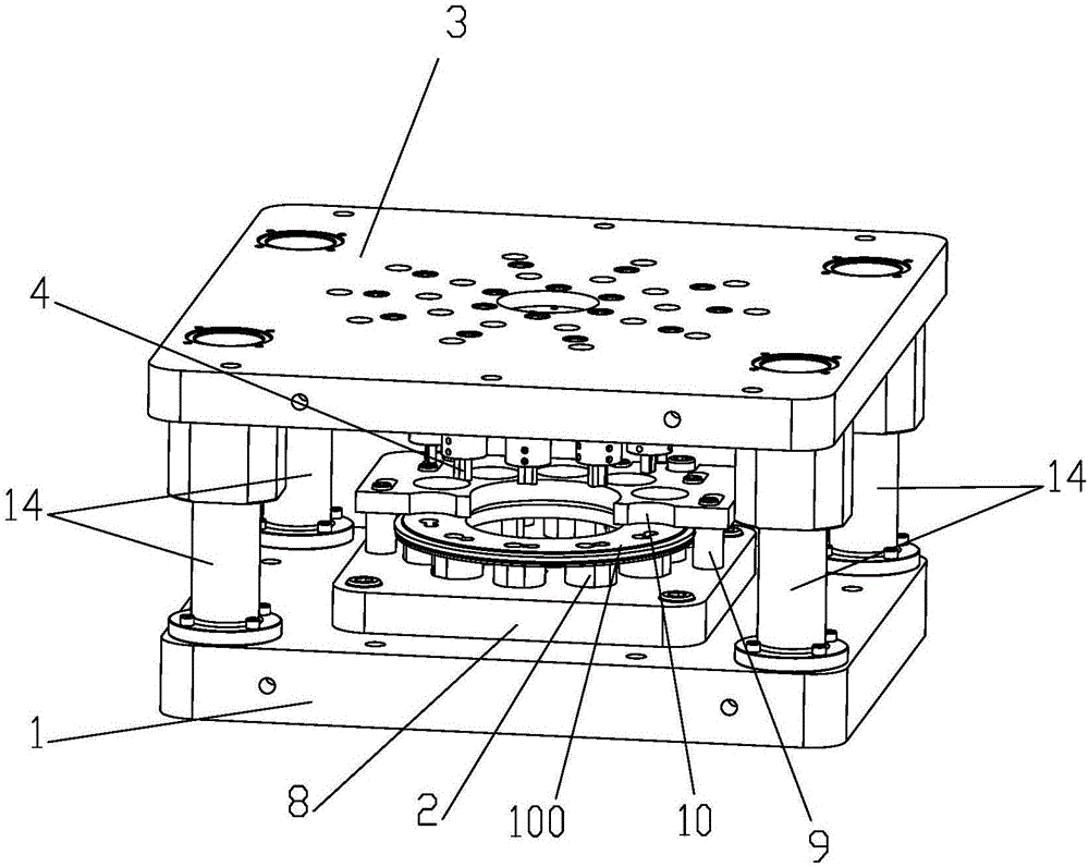
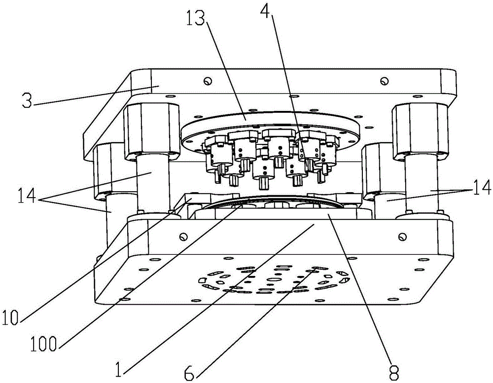
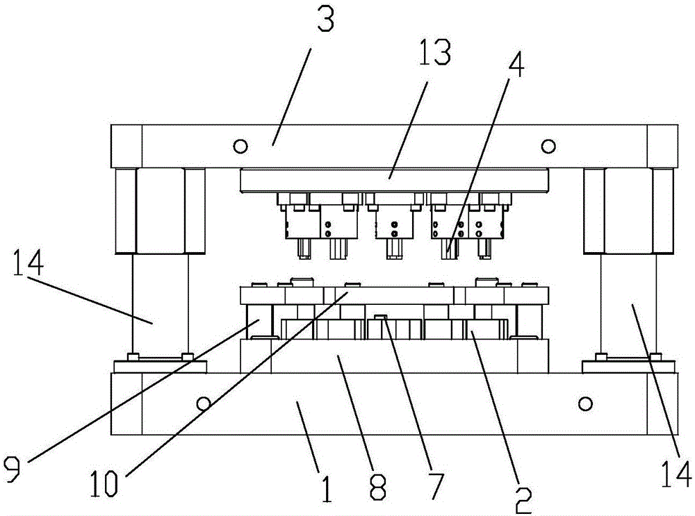
[0029] Such as Figure 1 to Figure 7 As shown, a combination punching die includes a lower die base 1, and the lower die base 1 is connected with a plurality of support die columns 2 capable of supporting the flange end plate 100 and arranged along the circumferential direction. The lower die base 1 is provided with an upper mold base 3 that can move up and down relative to it. The upper mold base 3 is connected with a plurality of support mold columns 2 that correspond one-to-one and can punch through holes 100a on the flange end plate 100. Punching pin 4, the support mold column 2 is provided with a discharge hole 5 for discharging waste when the punching pin 4 punches out of the through hole 100a, and the lower mold base 1 is provided with a discharge hole 5 communicating with the discharge hole 5. The discharge channel 6. In the punching process of the flange end plat...


PUM


Abstract

The invention discloses a combined mold. The combined mold comprises a lower mold base (1); the lower mold base (1) is connected with multiple support mold columns (2) capable of supporting a flange end plate (100) and arranged in the peripheral direction; an upper mold base (3) capable of moving up and down corresponding to the lower mold base (1) is arranged above the lower mold base (1), and is connected with multiple punching needles (4) corresponding to the support mold columns (2) one to one and capable of punching through holes (100a) in the flange end plate (100); and the support mold columns (2) are provided with discharge holes (5) for discharging wastes when the punching needles (4) punch the through holes (100a); and the lower mold base (1) is provided with discharge channels (6) communicated with the discharge holes (5). The combined mold is simple in structure, high in production efficiency and high in size precision of produced products.

Description

[0001] 【Technical field】 [0002] The invention relates to a combination die. [0003] 【Background technique】 [0004] The flange end plate is an important part of the pipe pile. During the processing of the flange end plate, it is necessary to punch out multiple through holes on the flange end plate. The traditional processing technology is that the punching machine punches through holes one by one on the flange end plate. When a through hole is punched, the flange end plate is rotated, and then the second through hole is punched, and so on. Punch the required number of through holes on the flange end plate. Therefore, the production efficiency is very low, and since the workpiece will be rotated and moved every time a through hole is punched, the positional and dimensional accuracy of the through holes is also low. [0005] Therefore, the present invention just produces based on above deficiency. [0006] 【Content of invention】 [0007] The object of the present invention...

Claims


Application Information

Patent Timeline
Patent Type & Authority Applications(China)
IPC IPC(8): B21D28/34B21D28/26B21D43/00
CPCB21D28/34B21D28/26B21D43/003
Inventor 尹定红樊金标杨向东肖修明蒋科胡泳涛张燕航
Owner 广东毅马集团有限公司
Why Eureka
Try Eureka