
Mud-rock flow disaster process rapid simulation and visualization analysis method in network environment

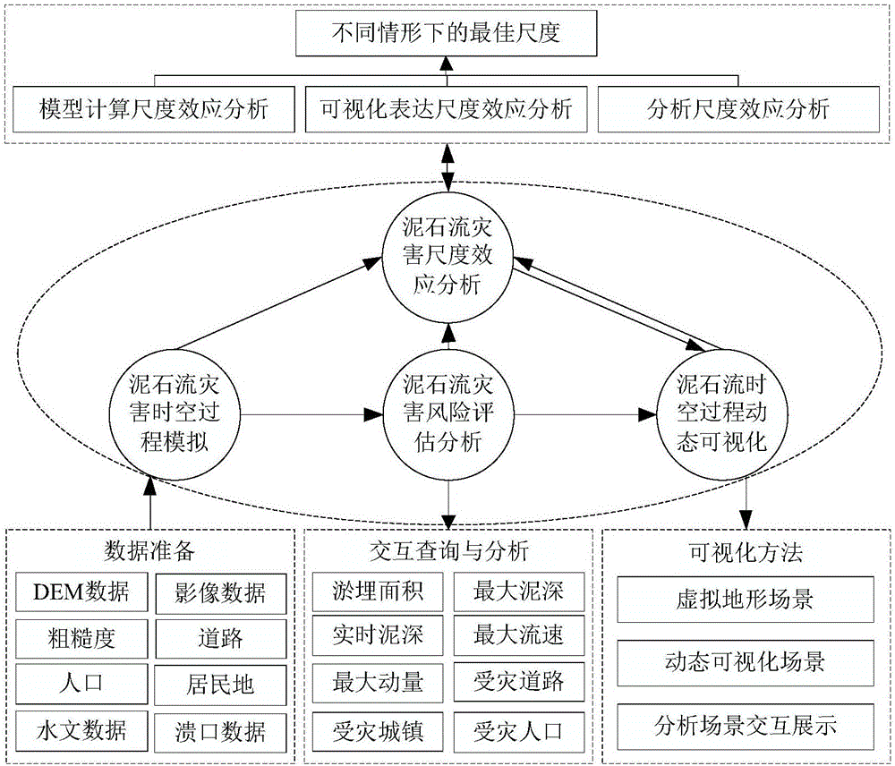
A network environment and analysis method technology, applied in the field of debris flow disaster simulation and visual analysis, can solve the problems of lack of debris flow disaster simulation and analysis tools, insufficient research on multi-source data sharing and integration, single desktop application program, etc., to facilitate dynamic interactive adjustment , improve accuracy and efficiency, and improve the effect of simulation calculation efficiency

Active Publication Date: 2017-05-17
朱军
View PDF3 Cites 15 Cited by
  • Summary
  • Abstract
  • Description
  • Claims
  • Application Information

AI Technical Summary

Problems solved by technology

However, the existing spatio-temporal process simulation, visualization and spatial analysis are separated, and there is insufficient research on the sharing and integration of multi-source data, models, and multi-disciplinary knowledge, and there is a lack of tools that can be used efficiently for debris flow disaster simulation and analysis
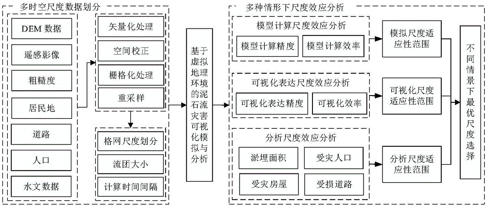
In addition, the spatio-temporal process of debris flow disasters only uses a single regular grid for visual simulation and analysis, and the choice of grid scale is also relatively random. Different grid scales will affect the efficiency and accuracy of model calculation, visualization, and analysis. How to strike a balance between accuracy and efficiency to select a suitable grid scale, lack of systematic research
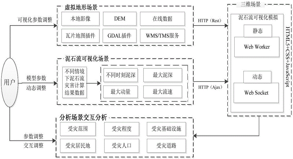
[0004] At present, most debris flow disaster simulations are based on a single desktop application, resulting in insufficient utilization and sharing of distributed storage data resources and model software, and most of them are limited to two-dimensional visualization. Lack of rich and real scene information

Method used


Image

  • Mud-rock flow disaster process rapid simulation and visualization analysis method in network environment
  • Mud-rock flow disaster process rapid simulation and visualization analysis method in network environment
  • Mud-rock flow disaster process rapid simulation and visualization analysis method in network environment

Examples


Embodiment example

[0085] (1) Selection of study areas for debris flow disasters

[0086] A typical debris flow disaster area was selected, with latitude and longitude as follows: 30°45′N~31°43′N, 102°51′E~103°44′E. This area includes a 15-kilometer main ditch and 8 branch ditches , the basin area of ​​this region is 54.2km2, and the altitude of the basin is between 1320 and 4360m. The main lithology in the watershed is granite and carbonatite. Affected by geological disasters, the rock mass disintegrated and the slope deposits slid down, which further increased the amount of loose deposits in the channel watershed. Debris flows were easily generated under the action of extreme rainfall. The continuous precipitation fully saturates the soil, and the instability and damage flow into the mountain torrents to form a debris flow. During the movement of the debris flow, the debris flow of the tributaries continues to flow in, and the upstream dammed lake partially collapses, eventually forming a larg...


PUM


Abstract

The present invention belongs to the geographic information system virtual geographical environment research field, and especially relates to a mud-rock flow disaster simulation and visualization analysis technology. The present invention provides a mud-rock flow disaster process rapid simulation and visualization analysis method in a network environment. The method performs tight integration of the model, the visualization and the analysis and provides a parameter visualization arrangement interface to facilitate obtaining and setting of parameters; and moreover, the mud-rock flow disaster process rapid simulation and visualization analysis method in the network environment employs a parallel optimization method and a scale optimization selection method to greatly improve the accuracy and efficiency of the simulation calculation, the visualization and the analysis of the mud-rock flow disaster, constructs the network service and provides sharing and publishing of the disaster situation information so as to effectively support the emergency disposal of the mud-rock flow disaster.

Description

technical field [0001] The invention belongs to the field of virtual geographic environment research of geographic information systems, and in particular relates to mud-rock flow disaster simulation and visualization analysis technology. Background technique [0002] Debris flow is a geological disaster that occurs frequently in mountainous areas. It is often caused by landslides caused by heavy rainfall in a short period of time. Its occurrence and development seriously threaten people's lives and property safety, and at the same time cause serious damage to the ecological environment of the affected areas. Carrying out the simulation and analysis of the spatio-temporal process of debris flow disasters can predict the propagation and evolution process of debris flows, obtain disaster information such as mud depth and flow velocity, determine the silting area and the degree of damage of debris flow disasters, and provide technical support for formulating emergency rescue and...

Claims


Application Information

Patent Timeline
IPC IPC(8): G06T17/05G06T17/20G06T1/20G06F17/50G06F17/30G06Q50/26H04L29/08
CPCG06F16/903G06F30/23G06Q50/265G06T1/20G06T17/05G06T17/20H04L67/12
Inventor 朱军朱庆
Owner 朱军
Learn More