
Phase angle drawing device for electric power

A phase angle, power technology, applied in printing, writing utensils and other directions, can solve the problems of low drawing accuracy and efficiency, and achieve the effect of efficient drawing, avoiding errors and easy to use

Active Publication Date: 2017-03-22
RES INST OF ECONOMICS & TECH STATE GRID SHANDONG ELECTRIC POWER +1
View PDF6 Cites 0 Cited by
  • Summary
  • Abstract
  • Description
  • Claims
  • Application Information

AI Technical Summary

Problems solved by technology

At present, when drawing the phase angle, it is generally drawn by a ruler or a triangle ruler. In this way, the drawing accuracy and efficiency are relatively low

Method used


Image

  • Phase angle drawing device for electric power
  • Phase angle drawing device for electric power
  • Phase angle drawing device for electric power

Examples


Embodiment Construction

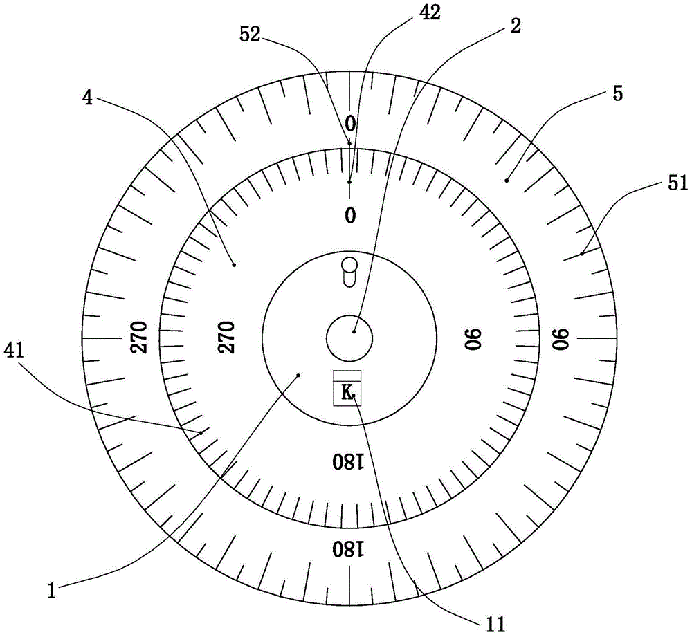
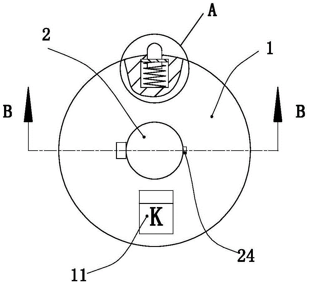
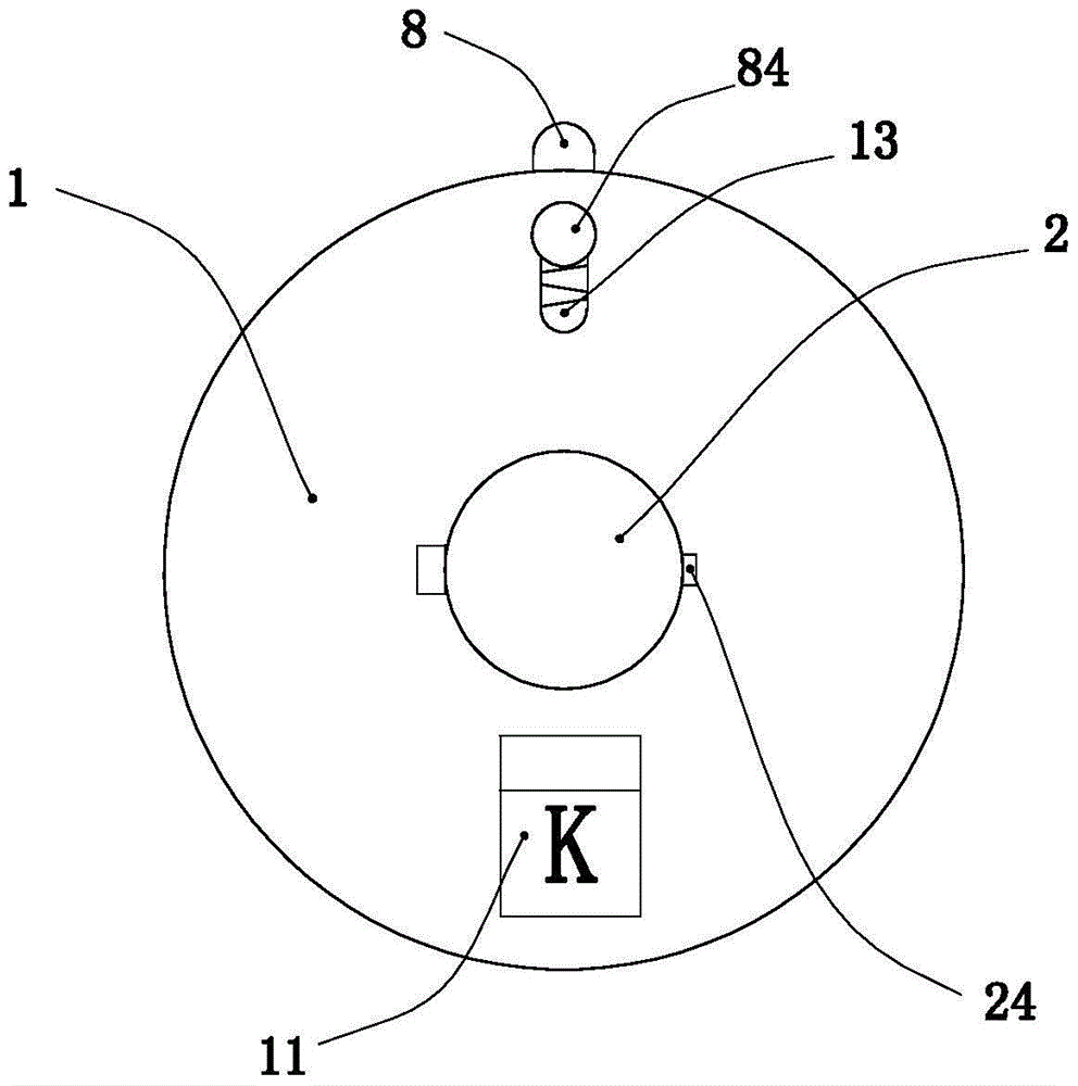
[0028] Such as Figure 1 to Figure 12 As shown, the present invention mainly includes a base 1, a movable rod 2, a lamp holder 22, an inner plate 4, an outer plate 5 and a positioning assembly. The present invention will be described in detail below with reference to the accompanying drawings.

[0029] Such as figure 2 As shown, the base 1 is a circular transparent plastic part, such as Figure 6 As shown, a vertically placed support rod 12 is provided on the top of the base, and the axis of the support rod is arranged in line with the axis of the base. Be provided with movable rod 2 on the support rod, the movable rod is a circular plastic rod, is provided with a slideway 21 on the axis of the movable rod, the top of the support rod is placed in the slideway and is slidably connected with the slideway, and the movable rod can be relatively The support rod rotates and moves up and down; for realizing the relative fixing of the movable rod and the support rod, a top wire 26 ...


PUM


Abstract

The invention discloses a phase angle drawing device for power, and the phase angle drawing device is used for realizing efficient and precise drawing for a phase angle. From the center of the top of a base, a supporting rod is upwards extended; a movable rod is arranged on the supporting rod; a jack screw is arranged between the supporting rod and the movable rod; the outer wall of the movable rod is provided with a lamp holder support; a lamp holder is mounted in the lamp holder support in a hinged mode; a lamp tube is arranged in an inner cavity of the lamp holder; a tapered seam is formed in the lamp holder; a switch is arranged on the base; the switch, the lamp holder and a storage battery on the base form an illuminating current loop; a positioning assembly is arranged between an inner plate and the base; the side edge of the inner plate is provided with inner scale marks; the outer plate can be mounted on the inner plate in a relatively rotary mode; and the outer plate is provided with outer scale marks. The device is convenient and simple in use, and capable of efficiently realizing phase angle drawing.

Description

technical field [0001] The invention relates to the technical field of electric power tools, in particular to a phase angle drawing device for electric power. Background technique [0002] In electrical design, plotting phase angles is a common task. At present, when drawing the phase angle, it is generally drawn by a ruler or a triangle ruler. In this way, the drawing accuracy and efficiency are relatively low. Therefore, there is an urgent need for a phase angle drawing device that is easy to use and has high drawing precision, so as to facilitate the drawing of the phase angle. Contents of the invention [0003] The purpose of the present invention is to provide a phase angle drawing device for electric power, which is used to realize efficient and accurate drawing of the phase angle. [0004] The technical solution adopted by the present invention to solve the technical problem is: a phase angle drawing device for electric power, which is characterized in that it inc...

Claims


Application Information

Patent Timeline
Patent Type & Authority Patents(China)
IPC IPC(8): B43L13/00
Inventor 康耕强戚峰宋兰兰薛炳磊
Owner RES INST OF ECONOMICS & TECH STATE GRID SHANDONG ELECTRIC POWER
Learn More