


Quick Research
Generate reliable direction feasibility study reports for your R&D in just a few steps.

Technical Q&A
Discover and master advanced knowledge NOW. Basics, ideas, possibilities, all at once.

Find Solutions
As an expert in R&D theories, this can generate solutions to your technical problems instantly.

Evaluate Feasibility
Analyze your overall solution with one click, know your potential R&D risks in advance.

Monitor Landscape
Get weekly tech updates, stay abreast of the latest tech innovations and key insights.
A two-way dust collection device for textile
The technology of a vacuum device and a vacuum tube, which is applied in the textile field, can solve the problems of easy shedding of lint, troubles, residues, etc., and achieve the effect of accelerating the drying speed
- Summary
- Abstract
- Description
- Claims
- Application Information
AI Technical Summary
Problems solved by technology
Method used
Image

Examples
Embodiment 1
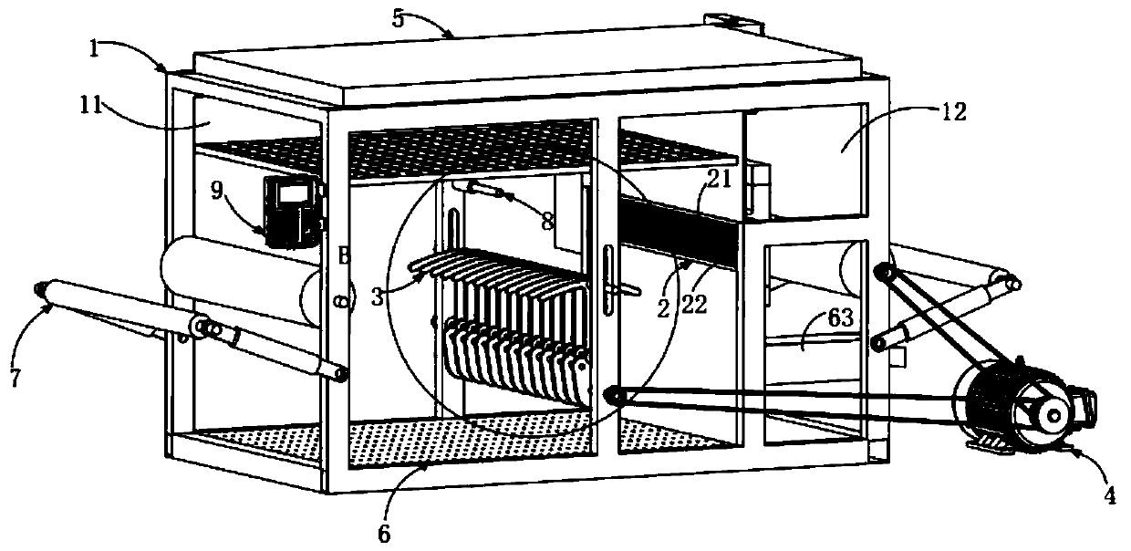
[0034] Such as figure 1 As shown, a two-way vacuum device for textiles includes:
[0035] A box body 1, the box body 1 includes a drying room 11 and a dust collection room 12; and
[0036]Two-way dust suction mechanism 2, the two-way dust suction mechanism 2 is arranged in the described dust suction chamber 12, and it includes the upper dust suction assembly 21 and the lower dust suction assembly 22 that are arranged correspondingly, and the upper dust suction assembly 21 and the lower suction assembly There is a gap between the dust components 22 for textiles to pass through, and the two-way dust suction mechanism 2 is used to vacuum and remove dust from the upper and lower surfaces of the textiles;
[0037] Swing mechanism 3, the swing mechanism 3 is arranged in the drying chamber 11, it is located in front of the two-way dust suction mechanism 2, the swing mechanism 3 is used to swing the textiles in the drying chamber 11, Force the impurity and dust on the textile to dro...
Embodiment 2
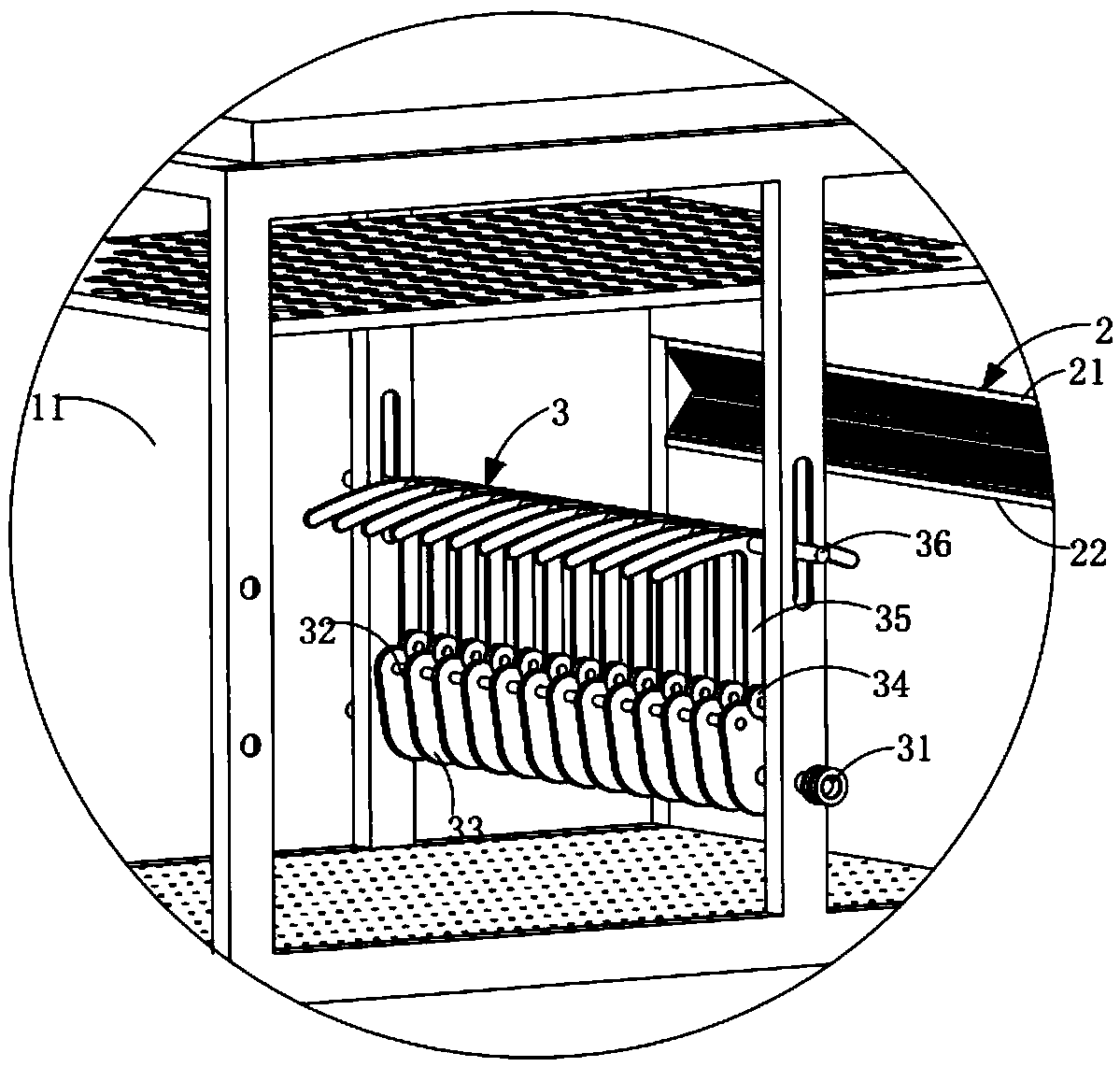
[0066] Such as image 3 As shown, as a preferred embodiment, the swing mechanism 3 includes several swing units, and the swing units include:
[0067] a cam 33, the cam 33 is arranged in the drying chamber 11; and
[0068] A roller 34, the roller 34 is correspondingly arranged on the edge of the cam 32, and the roller 34 is rollingly matched with the edge of the cam 32;
[0069] The swing arm 35 is hinged to the roller 34, the cam 33 rotates, and the roller 34 drives the swing arm 35 to swing up and down.
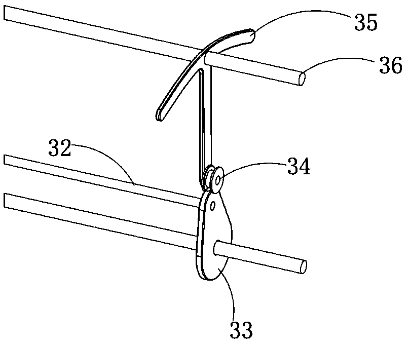
[0070] Such as figure 2 As shown, the swing mechanism 3 also includes:
[0071] Camshaft 31, said camshaft 31 is rollingly arranged on said drying chamber 11, said several oscillating units are fixedly arranged on said camshaft 31 through cam 33, and one end of said camshaft 31 is connected with said driving mechanism 4 connection; and
[0072] A cam synchronous shaft 32, the cam synchronous shaft 32 is arranged parallel to the cam shaft 31, and the cam 33 is connecte...
Embodiment 3
[0076] Such as Figure 7 As shown, as an improved technical solution, the heat exchange air outlet mechanism 6 includes a total heat exchanger 63, and the air inlet 631 of the total heat exchanger 63 is connected to the heating air supply mechanism 5 through the air inlet pipe 54, The air outlet 632 is connected to the heat exchange and air outlet mechanism through the air outlet pipe 62, and the outdoor low-temperature and dry cold air and the indoor high-temperature and humid hot air exchange heat through the total heat exchanger. Experimental tests show that the heat exchange rate of the total heat exchanger 63 is Up to 60%-80%.
[0077] Furthermore, the heat recovery method of the present invention is not limited to the above-mentioned embodiment, and the above-mentioned embodiment is only a preferred embodiment.
PUM
 Abstract
Description
Claims
Application Information
 - R&D Engineer
- R&D Manager
- IP Professional
- Industry Leading Data Capabilities
- Powerful AI technology
- Patent DNA Extraction
Browse by: Latest US Patents, China's latest patents, Technical Efficacy Thesaurus, Application Domain, Technology Topic, Popular Technical Reports.
© 2024 PatSnap. All rights reserved.Legal|Privacy policy|Modern Slavery Act Transparency Statement|Sitemap|About US| Contact US: help@patsnap.com