Eureka AIR delivers breakthrough ideas for toughest innovation challenges, trusted by R&D personnel around the world.

Oven

A technology for ovens and cabinets, which is applied in the field of ovens. It can solve the problems of long time, long heating and cooling time, and unusable heat, so as to reduce the heating and cooling time, reduce the heating time, and reduce the baking cost.

Inactive Publication Date: 2017-05-17
OPTIMUM BATTERY CO LTD
View PDF0 Cites 4 Cited by
  • Summary
  • Abstract
  • Description
  • Claims
  • Application Information

AI Technical Summary

Problems solved by technology

[0005] 1. Uneven heating: the local temperature of the heating wire is high, and the temperature of the place far away from the heating wire is relatively low, which leads to inconsistent effects of water removal during battery cell baking and affects the baking effect
[0006] 2. Long heating and cooling time: the rate of radiation heating is low, and the conversion efficiency is low; it takes a long time to rely on the natural cooling of the box to cool down
[0007] 3. Poor heat preservation effect: the commonly used electric core oven has no special heat preservation device, and it is difficult to maintain the temperature in the oven
[0008] 4. The heat lost by cooling cannot be used: by natural cooling, the heat is taken away by the outside air and cannot be recycled, which increases the cost of cell baking

Method used


Image

  • Oven
  • Oven
  • Oven

Examples


Embodiment Construction

[0029] In order to make the object, technical solution and beneficial technical effects of the present invention clearer, the present invention will be further described in detail below in conjunction with the accompanying drawings and specific embodiments. It should be understood that the specific implementations described in this specification are only for explaining the present invention, not for limiting the present invention.

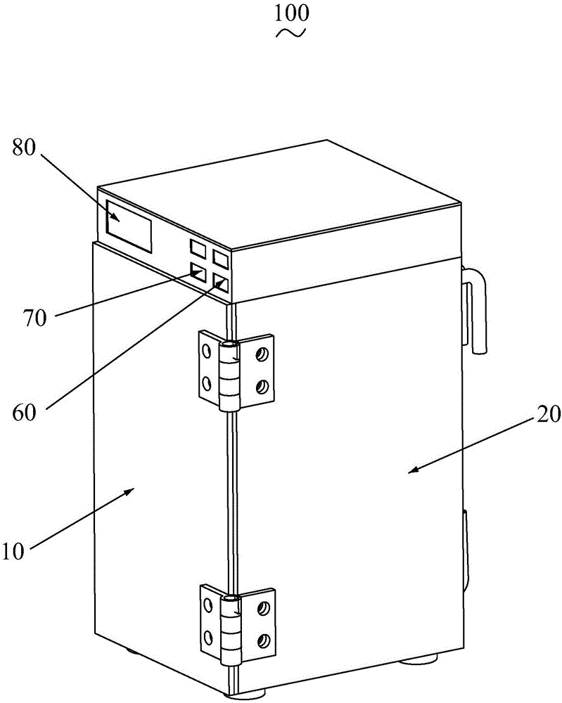
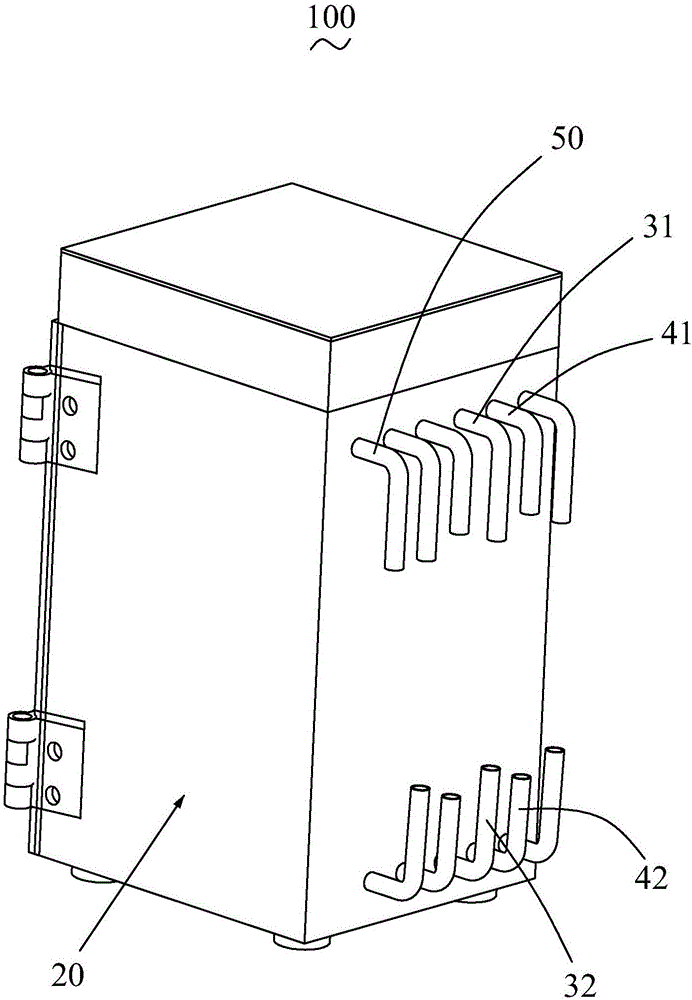
[0030] Please refer to figure 1 and figure 2 , The present invention provides an oven 100, comprising a box body 10 with one side open, a door 20, an upper infusion tube 31, a lower infusion tube 32, an upper ventilation tube 41, a lower ventilation tube 42 and a vacuum tube 50.

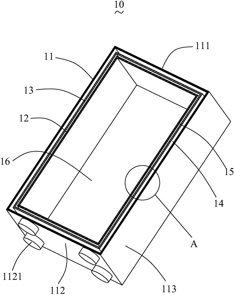
[0031] Please also refer to image 3 and Figure 4 , the box body 10 includes an outer wall 11 , an inner wall 12 sleeved in the outer wall 11 , and an interlayer 13 located between the outer wall 11 and the inner wall 12 and spaced from the outer wall 11 and the inne...


PUM


Abstract

The invention provides an oven. The oven comprises an oven body with an opening in one side, an oven door, an upper liquid delivery pipe, a lower liquid delivery pipe, an upper ventilation pipe, a lower ventilation pipe and a vacuum pipe, wherein the oven body comprises an outer wall, an inner wall arranged in the outer wall in a sleeving manner, and a sandwich layer which is located between the outer wall and the inner wall and is spaced from the outer wall and the inner wall; an airtight outer hollow layer is enclosed by the outer wall and the sandwich layer, and an airtight inner hollow layer is enclosed by the sandwich layer and the inner wall; one side of the oven door is movably connected with the oven body, the oven door can be in seal fit with the oven body, and an inner space is formed by the oven door and the inner wall; the upper liquid delivery pipe and the lower liquid delivery pipe are separately located at the two ends of the oven body and communicate with the inner hollow layer; the upper liquid delivery pipe, the lower liquid delivery pipe and the inner hollow layer are used for the circulation of heat conducting liquid; the upper ventilation pipe and the lower ventilation pipe are separately located at the two ends of the oven body and communicate with the inner space, and the upper ventilation pipe, the lower ventilation pipe and the inner space are used for the circulation of dry air; and the vacuum pumping pipe communicates with the outer hollow layer.

Description

[0001] 【Technical field】 [0002] The invention relates to the technical field of baking equipment, in particular to an oven. [0003] 【Background technique】 [0004] Lithium batteries are widely used in many fields, especially the electronics industry, due to their outstanding characteristics such as high working voltage, large specific energy, and small self-discharge. Moisture control is very critical in the production process of lithium batteries. Whether it is a wound structure battery or a laminated battery, the battery needs to be baked to remove the moisture in each material before liquid injection. At present, the industry generally adopts electric heating ovens for baking, while electric heating ovens use electric heating wires for heating, and there are the following defects: [0005] 1. Uneven heating: the local temperature of the heating wire is high, and the temperature of the place far away from the heating wire is relatively low, which leads to inconsistent eff...

Claims


Application Information

Patent Timeline
IPC IPC(8): F26B9/06F26B25/12F26B21/12F26B23/10F26B21/00
CPCF26B9/06F26B21/004F26B21/12F26B23/10F26B25/12
Inventor 朱政傅昭
Owner OPTIMUM BATTERY CO LTD
Why Eureka
Eureka Blog
Learn More