
Cooling system and control method thereof

A technology of a cooling system and a control method, which is applied in the control of coolant flow, cooling of the engine, fault prevention, etc., can solve the problems of large fan energy consumption, increased energy consumption of the whole machine, and energy waste.

Active Publication Date: 2017-05-17
SHANTUI CONSTR MASCH CO LTD
View PDF5 Cites 15 Cited by
  • Summary
  • Abstract
  • Description
  • Claims
  • Application Information

AI Technical Summary

Problems solved by technology

Its structure is simple, its performance is reliable, and its cost is low, but it has the following major defects: ①The starting torque of the engine is large, and the warm-up time is long; ②The fan consumes a lot of energy; Heat load or cold wear; ④ The installation position of the fan is severely restricted; ⑤ Generates serious noise
However, there are also the following major defects: ①The efficiency of the hydraulic drive system is affected by many factors such as pumps, motors, and pipelines, and the overall efficiency is relatively low. While increasing the energy consumption of the whole machine, it also increases the heat dissipation of the hydraulic system; ②Due to Due to factors such as cost and space layout, it is difficult to realize the independent fan cooling control of multiple cooling modules such as engine radiator, air-to-air cooler, and working oil cooler on construction machinery, and it is impossible to make each system reach the best working temperature;③ In order to realize the fast response of the fan and reduce the impact of the sudden increase of torque on the liquid drive system, even when the heat dissipation modules rely on natural heat dissipation to meet the heat dissipation requirements, the fan is still running at a low speed, which causes a certain amount of energy waste; ④ At the same time, there are also disadvantages such as high maintenance cost, poor maintainability, and complex structure.

Method used


Image

  • Cooling system and control method thereof
  • Cooling system and control method thereof
  • Cooling system and control method thereof

Examples


Embodiment Construction

[0035] The technical solutions of the present invention will be further described below in conjunction with the accompanying drawings and through specific implementation methods.

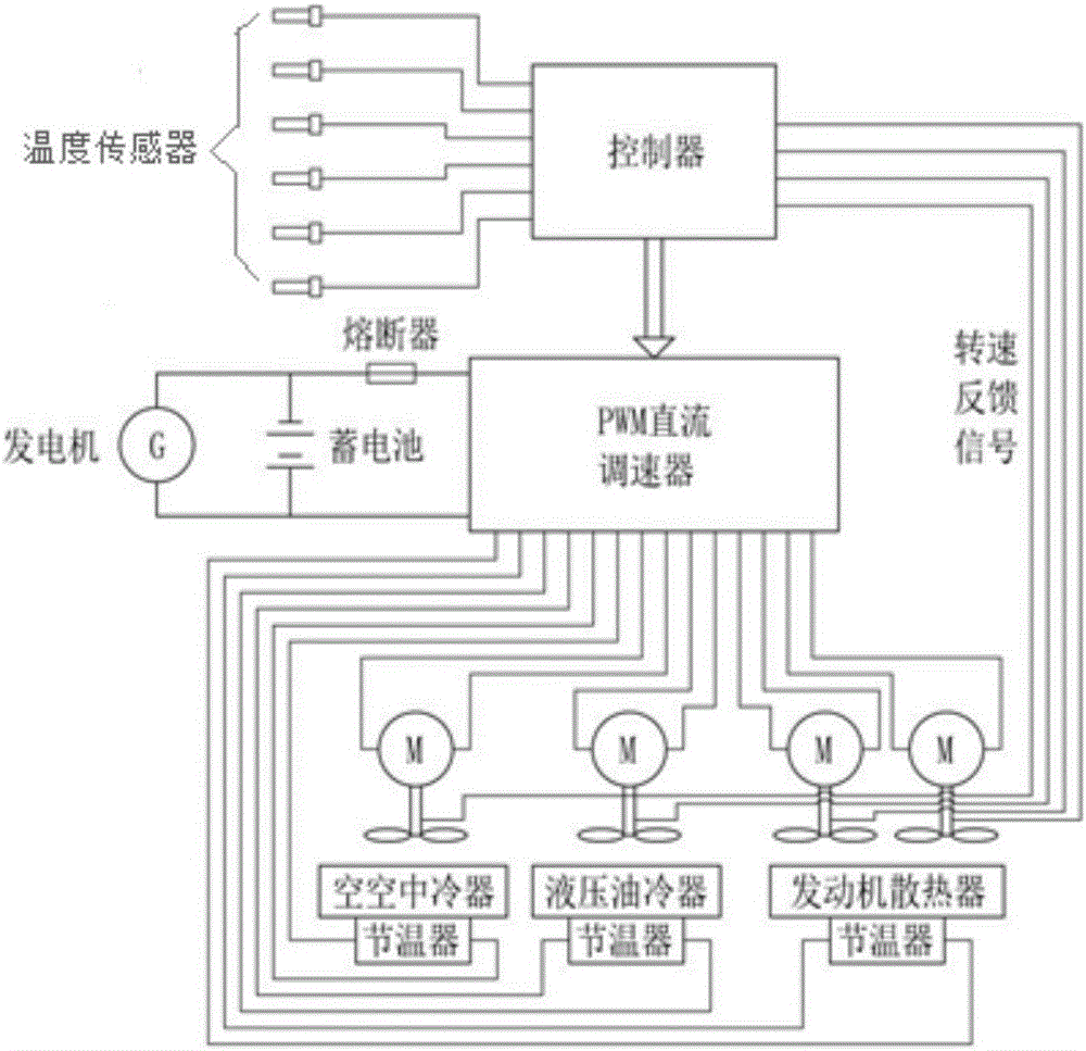
[0036] Such as figure 1 As shown, the present invention provides a cooling system, including a controller, a temperature sensor, a PWM DC governor, a thermostat, a fan and a speed sensor, wherein:

[0037] Each heat dissipation module is provided with an independent temperature sensor for detecting the temperature signal of the heat dissipation module. Each temperature sensor only acts on the fan of the corresponding heat dissipation module. In this embodiment, the heat dissipation module includes an engine radiator, Hydraulic oil cooler and air-to-air cooler, etc.;

[0038] The controller is connected to the temperature sensor, and the controller sends a control signal to the PWM DC speed controller connected to it through the temperature signal. Function, there is a fuse on the connection circui...


PUM


Abstract

The invention relates to the technical field of engineering machinery, in particular to a cooling system and a control method thereof. The cooling system comprises a controller, temperature sensors, a pulse width modulation (PWM) direct-current speed controller, thermostats, fans and a rotation speed sensor. All heat dissipation modules are independently provided with the temperature sensors, the thermostats and the fans. The temperature sensor can monitor the temperatures of all the heat dissipation modules in real time. The controller gives out a control signal to the PWM direct-current speed controller according to a temperature signal. The PWM direct-current speed controller can adjust the thermostats of all the heat dissipation modules to be turned on or turned off and can also adjust the rotation speeds of the fans according to the control signal. In this way, a complete machine is reasonably controlled to dissipate heat in real time, all the heat dissipation modules of the complete machine are kept in the most ideal temperature ranges all the time, meanwhile, the power consumption of the fans is reduced to the greatest extent, and the efficiency of the complete machine is improved.

Description

technical field [0001] The invention relates to the technical field of engineering machinery, in particular to a cooling system and a control method. Background technique [0002] Construction machinery is mainly used in complex and harsh working conditions such as earthwork construction and engineering construction, and has a large operating load. Therefore, the engine often works at high speed and high torque. Due to the power loss of torque converters, gearboxes and other transmission parts, the whole The cooling power of the machine is relatively large. At the same time, construction machinery is used in a wide range of regions, and it needs to adapt to different environments such as extreme cold and high temperature, and has good environmental adaptability. The above factors put forward relatively high requirements on the cooling system of construction machinery. [0003] At present, the cooling system commonly used in construction machinery mainly has two structures,...

Claims


Application Information

Patent Timeline
IPC IPC(8): F01P7/16F01P7/04F01P11/16
CPCF01P7/048F01P7/16F01P11/16F01P2025/64F01P2031/20F01P2060/02F01P2060/045
Inventor 张明月倪令华刘春朝宋琳莹纪红吴振
Owner SHANTUI CONSTR MASCH CO LTD
Learn More