An automatic shielding device for parking a car
An automatic, automotive technology, applied in the direction of parking buildings, building types, buildings, etc., can solve the problems of freezing, affecting the performance of the car and the environment of the cab, achieving high versatility, easy to popularize and use, and manufacturing costs. low cost effect
- Summary
- Abstract
- Description
- Claims
- Application Information
AI Technical Summary
Problems solved by technology
Method used
Image
Examples
specific Embodiment approach 1
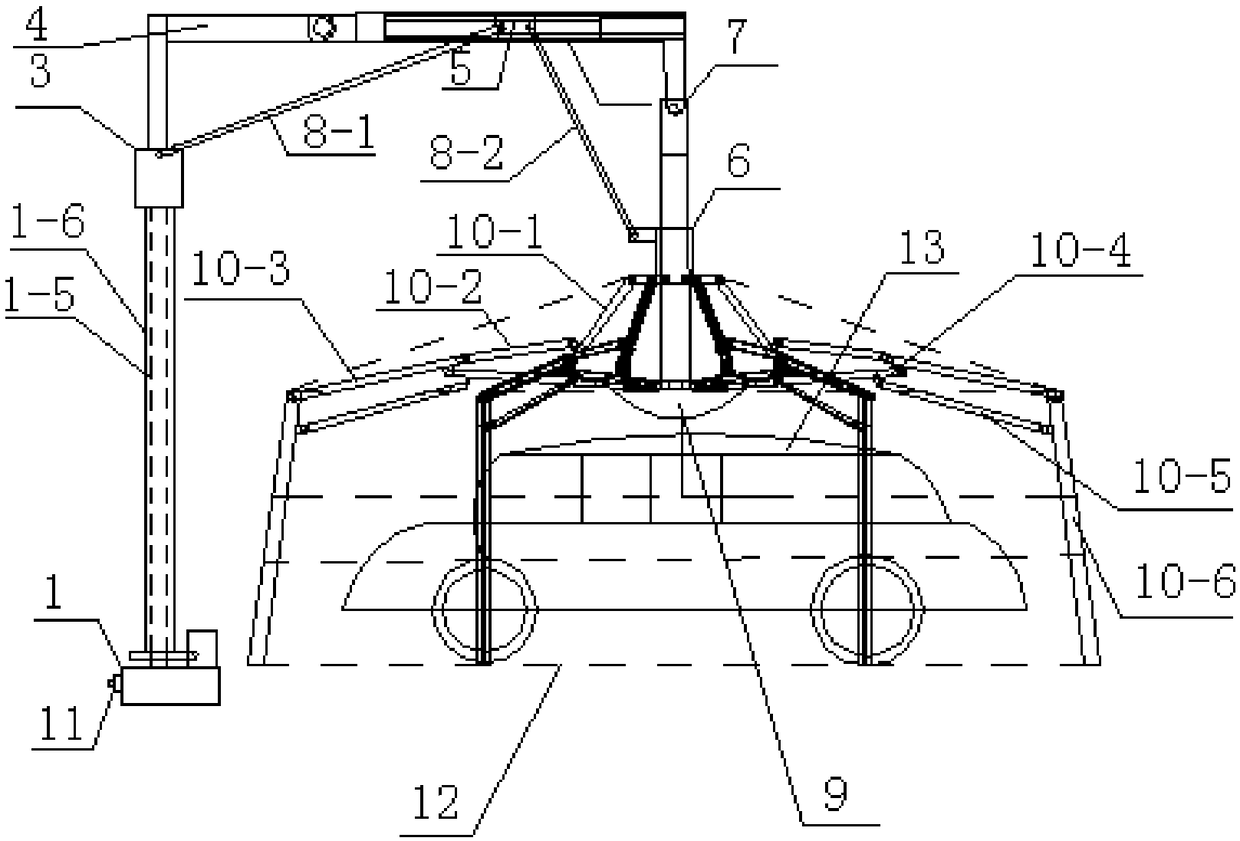
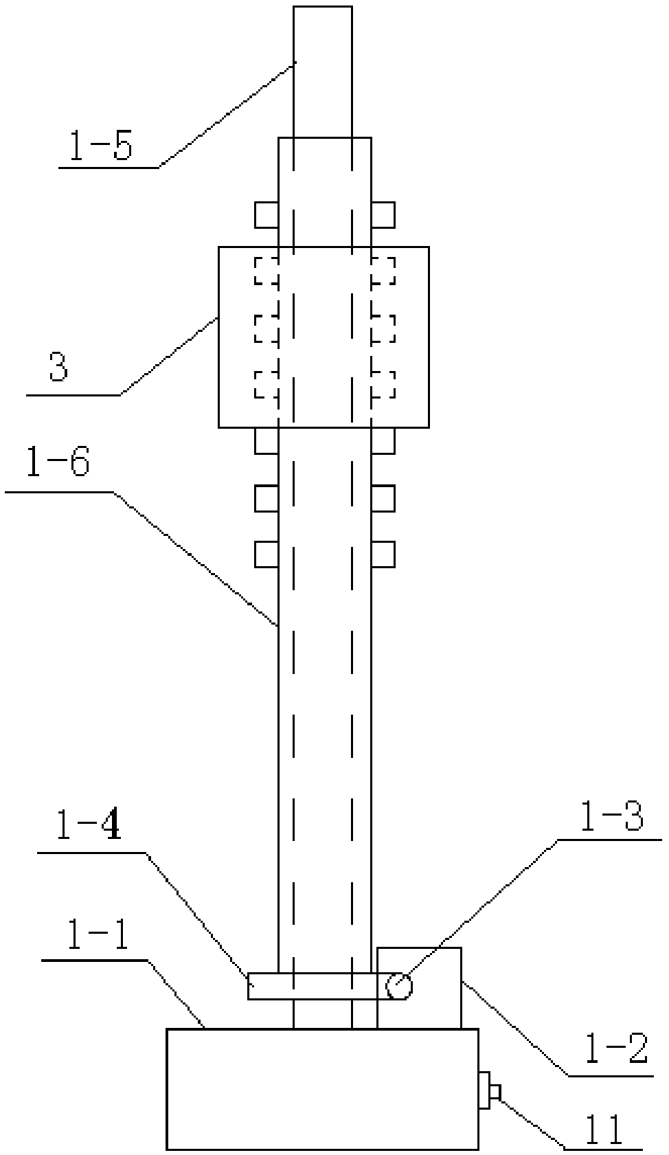
[0023] Specific implementation mode one: combine figure 1 , figure 2 , image 3 with Figure 4 Describe this embodiment, this embodiment comprises drive type base 1, foldable support assembly, hinged support assembly, umbrella cover support frame and shade cover 12, and described drive type base 1 is fixedly installed on the ground, and described drive type base 1 is provided with a foldable support assembly, the foldable support assembly is provided with a hinged support assembly, the foldable support assembly is connected with the support frame for the umbrella cover through the hinge support assembly, and the shield cover 12 is arranged on the support frame for the umbrella cover. shelf;
[0024] The drive base 1 includes a base body 1-1, a motor 1-2, a worm 1-3, a worm wheel 1-4, a positioning rod 1-5 and a transmission sleeve 1-6, and the base body 1-1 is fixedly installed on the ground , the positioning rod 1-5 is vertically arranged and its lower end is fixedly con...
specific Embodiment approach 2
[0028] Specific implementation mode two: combination figure 1 Describe this embodiment, in this embodiment, the folding support assembly includes a spiral sleeve 3, a horizontal support rod 4, a sliding sleeve 5, an umbrella top cover 6, a rotating rod 7 and a shield 9, and the rotating rod 7 is connected to the positioning rod 1- 5 are vertically arranged side by side, and the horizontal support rod 4 is horizontally arranged between the positioning rod 1-5 and the rotating rod 7. The upper end of the positioning rod 1-5 is fixedly connected with one end of the horizontal support rod 4, and the other end of the horizontal support rod 4 One end is connected with the upper end of the rotating rod 7, the lower end of the rotating rod 7 passes through the umbrella top cover 6 and is connected with the visor 9, the umbrella top cover 6 is slidingly matched with the rotating rod 7, and the transmission sleeve 1-6 is covered with a spiral sleeve 3 And the two are threaded, the helic...
specific Embodiment approach 3
[0029] Specific implementation mode three: combination figure 1 Describe this embodiment. In this embodiment, the hinge support assembly includes a first connecting rod 8-1 and a second connecting rod 8-2. The first connecting rod 8-1 is obliquely arranged between the spiral sleeve 3 and the sliding sleeve 5 , one end of the first connecting rod 8-1 is hinged with the spiral sleeve 3, and the other end of the first connecting rod 8-1 is hinged with the sliding sleeve 5; the second connecting rod 8-2 is obliquely arranged at Between the sliding sleeve 5 and the umbrella top cover 6 , one end of the second connecting rod 8 - 2 is hinged to the sliding sleeve 5 , and the other end of the second connecting rod 8 - 2 is hinged to the outer wall of the umbrella top cover 6 . Other compositions and connections are the same as in the second embodiment.
PUM
 Abstract
Description
Claims
Application Information
 - R&D
- Intellectual Property
- Life Sciences
- Materials
- Tech Scout
- Unparalleled Data Quality
- Higher Quality Content
- 60% Fewer Hallucinations
Browse by: Latest US Patents, China's latest patents, Technical Efficacy Thesaurus, Application Domain, Technology Topic, Popular Technical Reports.
© 2025 PatSnap. All rights reserved.Legal|Privacy policy|Modern Slavery Act Transparency Statement|Sitemap|About US| Contact US: help@patsnap.com


