Eureka AIR delivers breakthrough ideas for toughest innovation challenges, trusted by R&D personnel around the world.

Stereoscopic vision orifice plate and manufacturing equipment thereof

A technology for stereo vision and manufacturing equipment, which is applied in advertising, metal processing, instruments, etc., can solve the problems of high maintenance cost, many wearing parts, and single function, and achieve the goal of improving the scope of application, improving the scope of application, and improving processing efficiency Effect

Inactive Publication Date: 2021-03-16
上海迈饰新材料科技有限公司
View PDF7 Cites 0 Cited by
  • Summary
  • Abstract
  • Description
  • Claims
  • Application Information

AI Technical Summary

Problems solved by technology

[0002] Traditional advertising displays are generally displayed in the form of LEDs. This type of display product consumes a lot of energy, has many wearing parts, and high maintenance costs in the later period; while most of the current curtain walls are only used for decoration, with single functions, and cannot cope with weather changes; The display boards are mostly flat boards, which are only used for display effects; based on this, a board body is designed, which can be used for advertising display, and can be beneficially processed for different weather, and has a noise reduction function, which will realize a board Multi-purpose, and greatly reduce the cost of use, therefore, an improved technology is urgently needed to solve this problem in the prior art

Method used


Image

  • Stereoscopic vision orifice plate and manufacturing equipment thereof
  • Stereoscopic vision orifice plate and manufacturing equipment thereof
  • Stereoscopic vision orifice plate and manufacturing equipment thereof

Examples


Embodiment Construction

[0041] The technical solutions of the present invention will be clearly and completely described below with reference to the accompanying drawings in the embodiments of the present invention. Obviously, the described embodiments are only a part of the embodiments of the present invention, but not all of the embodiments. Based on the embodiments of the present invention, all other embodiments obtained by those of ordinary skill in the art without creative work fall within the protection scope of the present invention;

[0042]It should be noted that, in the description of the present invention, it should be noted that the terms "inner", "outer", "upper", "lower", "both sides", "one end", "the other end" and "left" The orientation or positional relationship indicated by "right" and the like is based on the orientation or positional relationship shown in the drawings, and is only for the convenience of describing the present invention and simplifying the description, rather than i...


PUM


Abstract

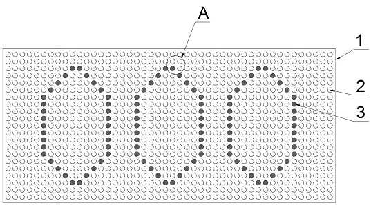
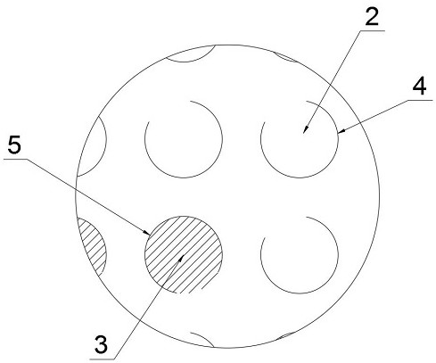
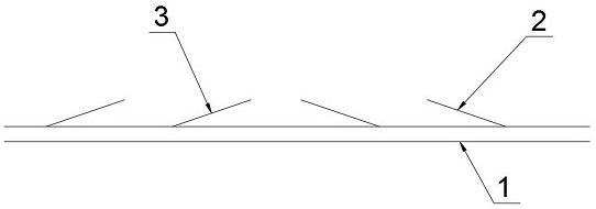
The invention discloses a stereoscopic vision orifice plate which comprises a plate body, a plurality of arc-shaped backlight notches and a plurality of arc-shaped light-facing notches are formed in the plate body, the plate body cut along the arc-shaped backlight notches is partially warped upwards to form a backlight wafer, the plate body cut along the arc-shaped light-facing notches is partially warped upwards to form a light-facing wafer, wherein the notch directions of the arc-shaped backlight notches are the same, the notch directions of the arc-shaped light-facing notches are the same,the notch directions of the arc-shaped light-facing notches and the arc-shaped backlight notches are opposite, and the warping direction of the backlight wafer is the same as and / or opposite to the warping direction of the light-facing wafer. The stereoscopic vision orifice plate is reasonable in structure, the backlight wafers and the light-facing wafers with reverse openings are densely distributed on the plate body, the stereoscopic vision orifice plate can be used for advertisement display, curtain wall installation and municipal roads, sun shading can be achieved in sunny days, rain prevention can be achieved in rainy days, ventilation can be achieved in windy days, and the yin-yang face effect can be achieved through the arrangement of the light-facing wafers and the backlight wafers; and therefore, three-dimensional LOGO, characters and patterns can be presented, and the effects of shading and multi-plate-body noise absorption are achieved.

Description

technical field [0001] The invention relates to the technical field of stereoscopic orifice plates, in particular to a stereoscopic orifice plate and its manufacturing equipment. Background technique [0002] Traditional advertising displays are generally displayed in the form of LEDs. Such display products have high energy consumption, many wearing parts, and high maintenance costs. At present, most of the curtain walls are only used for decoration, with a single function and cannot cope with weather changes; Display boards, mostly flat boards, are only used for display effects; based on this, a board body is designed, which can be used for advertising display, and can be beneficially processed for different weather, and has the function of noise reduction, which will realize a board It is multi-purpose and greatly reduces the cost of use. Therefore, an improved technology is urgently needed to solve this problem existing in the prior art. SUMMARY OF THE INVENTION [000...

Claims


Application Information

Patent Timeline
Patent Type & Authority Applications(China)
IPC IPC(8): G09F19/12B26F1/44B26F1/38B26D7/01B26D7/26
CPCG09F19/12B26F1/44B26F1/38B26D7/01B26D7/2628
Inventor 刘新宇
Owner 上海迈饰新材料科技有限公司
Why Eureka
Eureka Blog
Learn More