
Mechanical arm used for automatic sand blasting

A manipulator and sandblasting technology, applied in the field of manipulators, can solve the problems of unsatisfactory production, low sandblasting efficiency and high labor cost, and achieve the effects of simple structure, low labor cost and high work efficiency

Inactive Publication Date: 2017-05-17
ANHUI ZHILIANG INVESTMENT GRP
View PDF0 Cites 7 Cited by
  • Summary
  • Abstract
  • Description
  • Claims
  • Application Information

AI Technical Summary

Problems solved by technology

[0002] Sand blasting is through the impact and cutting effect of abrasives on the surface of the workpiece, so that the surface of the workpiece can obtain a certain degree of cleanliness and different roughness, so that the mechanical properties of the surface of the workpiece can be improved, thus improving the fatigue resistance of the workpiece and increasing its The adhesion between the coating and the coating prolongs the durability of the coating film, and is also conducive to the leveling and decoration of the coating. It removes impurities, variegated colors and oxide layers on the surface, and at the same time roughens the surface of the medium to eliminate the residual stress of the workpiece. And improve the surface hardness of the substrate. At present, the sandblasting treatment of the surface of the cylindrical workpiece is carried out by manual sandblasting. The sandblasting efficiency is low and cannot meet the production requirements. At the same time, manual sandblasting is used. way, its labor cost is higher

Method used


Image

  • Mechanical arm used for automatic sand blasting

Examples


Embodiment Construction

[0019] The following will clearly and completely describe the technical solutions in the embodiments of the present invention with reference to the accompanying drawings in the embodiments of the present invention. Obviously, the described embodiments are only some, not all, embodiments of the present invention.

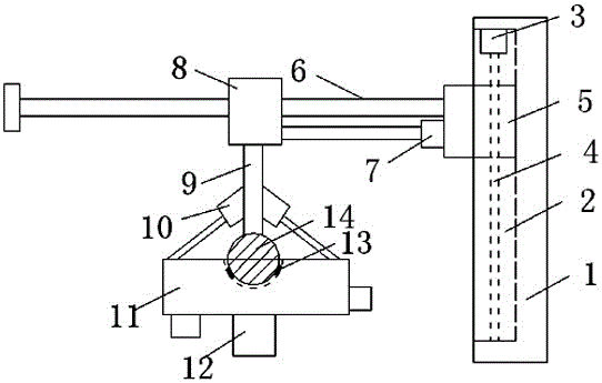
[0020] refer to figure 1 , a mechanical arm for automatic sandblasting, including a fixed seat 1, a linear slide rail 6 and a sandblasting installation plate 11, a first chute 2 is provided on the inner wall of one side of the fixed seat 1, and the first chute 2 A first sliding seat 5 is slidably connected to the inner wall, and one side of the first sliding seat 5 extends to one side of the fixed seat 1, and a first motor 3 is arranged above the first sliding seat 5, and the first motor 3 is fixedly installed On the top inner wall of the first chute 2, the output shaft of the first motor 3 is connected with a screw 4, and the bottom of the screw 4 is slidably connec...


PUM


Abstract

The invention discloses a mechanical arm used for automatic sand blasting. The mechanical arm comprises a fixed base, a linear sliding rail and a sand blasting mounting plate; a first sliding groove is formed in the inner wall of one side of the fixed base, a first sliding base is in sliding connection to the inner wall of the first sliding groove, one side of the first sliding base extends to one side of the fixed base, a first motor is arranged above the first sliding base, and is fixedly mounted on the inner wall of the top of the first sliding groove, an output shaft of the first motor is connected with a screw rod, and the bottom of the screw rod is in sliding connection with the inner wall of the bottom of the first sliding groove; the liner sliding rail is arranged on the side, away from the fixed base, of the first sliding base; the mechanical arm is simple in structure, economical, practical, low in manual cost and high in work efficiency, the mechanical arm use for automatic sand blasting can automatically adjust the distance between a sand blasting mounting plate and an object to be treated in the vertical direction and the horizontal direction, and the sand blasting effect of the mechanical arm used for automatic sand blasting is good.

Description

technical field [0001] The invention relates to the technical field of mechanical arms, in particular to a mechanical arm for automatic sandblasting. Background technique [0002] Sand blasting is through the impact and cutting effect of abrasives on the surface of the workpiece, so that the surface of the workpiece can obtain a certain degree of cleanliness and different roughness, so that the mechanical properties of the surface of the workpiece can be improved, thus improving the fatigue resistance of the workpiece and increasing its The adhesion between the coating and the coating prolongs the durability of the coating film, and is also conducive to the leveling and decoration of the coating. It removes impurities, variegated colors and oxide layers on the surface, and at the same time roughens the surface of the medium to eliminate the residual stress of the workpiece. And improve the surface hardness of the substrate. At present, the sandblasting treatment of the surfa...

Claims


Application Information

Patent Timeline
Patent Type & Authority Applications(China)
IPC IPC(8): B24C5/00B24C9/00G01B21/02
CPCB24C5/00B24C9/00G01B21/02
Inventor 王卫华
Owner ANHUI ZHILIANG INVESTMENT GRP
Learn More