
Boiler flue gas recirculation dehumidification device

A boiler flue gas and recirculation technology, applied in gas treatment, membrane technology, dispersed particle separation, etc., can solve problems such as safety hazards, achieve the effect of small pressure loss, eliminate safety hazards, and high dehumidification efficiency

Inactive Publication Date: 2017-05-17
SHANGHAI WISEBOND TECH
View PDF9 Cites 6 Cited by
  • Summary
  • Abstract
  • Description
  • Claims
  • Application Information

AI Technical Summary

Problems solved by technology

[0004] The purpose of the present invention is to solve the problem of potential safety hazards in the flue gas recirculation system caused by the existence of water vapor in the flue gas in cold weather, and to provide a high-efficiency dehumidification device for boiler flue gas recirculation

Method used


Image

  • Boiler flue gas recirculation dehumidification device
  • Boiler flue gas recirculation dehumidification device
  • Boiler flue gas recirculation dehumidification device

Examples


Embodiment Construction

[0014] The present invention will be further described below in conjunction with drawings and embodiments.

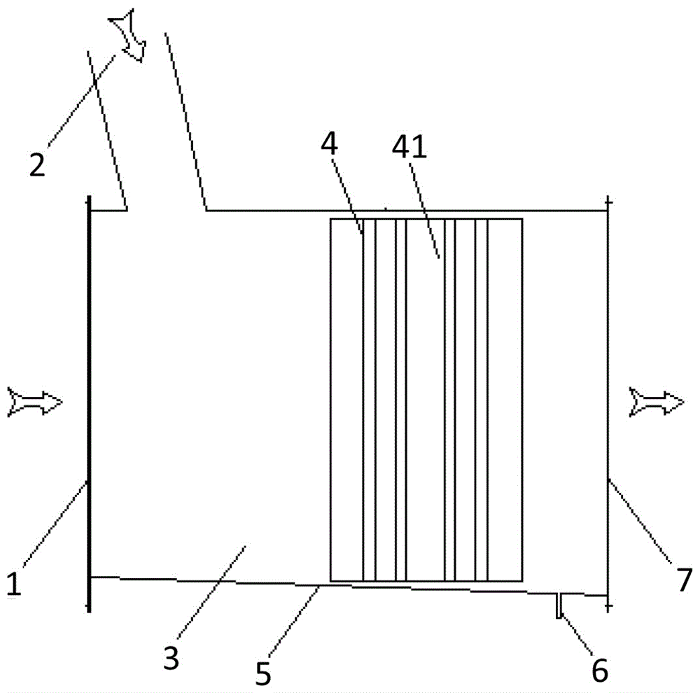
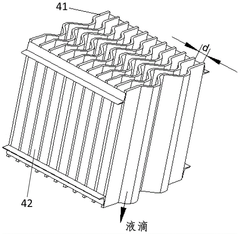
[0015] figure 1 It is a schematic diagram of the overall structure of the dehumidification device of the present invention. It can be seen from the diagram that a boiler flue gas recirculation dehumidification device includes a flue gas mixing box 3, a combustion air inlet 1 located at the head end of the flue gas mixing box 3, and The upper side wall of the head end of the flue gas mixing box 3 is obliquely inserted into the hot flue gas inlet pipe 2 in the inner cavity of the flue gas mixing box 3, and the mixed gas outlet 7 located at the tail end of the flue gas mixing box 3 is characterized in that: A mist eliminator 4 is fixedly installed in the middle and rear of the flue gas mixing box 3; the mist eliminator 4 is composed of a plurality of baffles 41 parallel to each other, arranged longitudinally, and leaving intervals 42(d) between them. The interval 42(d) be...


PUM


Abstract

The invention relates to a boiler flue gas recirculation dehumidification device in order to solve the security risks caused by the presence of water vapor in recirculated flue gas, and belongs to the technical field of boiler flue gas recirculation. The boiler flue gas recirculation dehumidification device is characterized in that a defogger is fixedly arranged in the middle rear part of the inside of a flue gas mixing tank and consists of a plurality of baffles arranged in parallel and longitudinally and spaced apart from each other; the direction of the space between the baffles is consistent with the flow direction of mixed gas, and one end of a groove formed by baffling of the baffles is fixedly connected with a bottom board of the flue gas mixing tank; the bottom board of the flue gas mixing tank tilts down from the head end to the tail end, and a water outlet pipe is arranged at the bottommost part of the bottom board. The boiler flue gas recirculation dehumidification device provided by the invention has the beneficial effects of simple structure, high dehumidification efficiency, and low pressure loss. In the process of dehumidification, the combustion air and hot flue gas are fully mixed, and the hidden dangers caused by humidification in a flue gas recirculation system are completely eliminated, so the application market is huge.

Description

technical field [0001] The invention relates to a flue gas recirculation dehumidification device for a boiler, in particular to a dehumidification device for removing part of the water vapor contained in the flue gas and combustion-supporting air in the flue gas recirculation technology, which belongs to the technical field of gas boiler flue gas recirculation . Background technique [0002] The national emission limits of air pollutants from industrial boilers and industrial furnaces are becoming more and more stringent. Gas and fuel oil are more and more used in industrial boilers, and flue gas recirculation technology can effectively reduce the NOx emission concentration of boilers, so it is widely used. [0003] Hot flue gas contains water vapor with a relatively high proportion, but the current flue gas recirculation system lacks a flue gas dehumidification device, and the hot flue gas is directly mixed with air and sent to the burner for combustion. When the outside ...

Claims


Application Information

Patent Timeline
Patent Type & Authority Applications(China)
IPC IPC(8): B01D53/26B01D45/08
CPCB01D45/08B01D53/265B01D2257/80B01D2258/0283
Inventor 陈宝明田莉勤刘佳云
Owner SHANGHAI WISEBOND TECH
Learn More