Measuring angle of incidence in an ultrawideband communication system

A signal and angle of arrival technology, applied in the field of receivers, which can solve problems such as large carrier phase

Active Publication Date: 2017-05-10
戴卡维夫有限公司
View PDF13 Cites 6 Cited by
  • Summary
  • Abstract
  • Description
  • Claims
  • Application Information

AI Technical Summary

Problems solved by technology

If the carrier frequency is high, for example, 4GHz or 6.5GHz, a relatively small distance p will result in a relatively large carrier phase difference

Method used


Image

  • Measuring angle of incidence in an ultrawideband communication system
  • Measuring angle of incidence in an ultrawideband communication system
  • Measuring angle of incidence in an ultrawideband communication system

Examples


Embodiment Construction

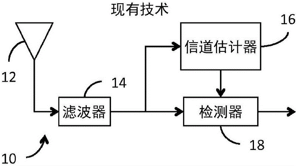
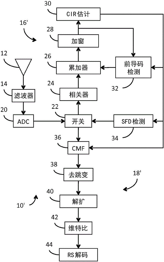
[0071] figure 2 A UWB receiver 10' constructed in accordance with the present invention is shown. Such as figure 1 As in the prior art system shown, the signal received by antenna 12 is continuously conditioned by filter 14 . The conditioned signal is then periodically sampled by an analog-to-digital converter ("ADC") 20 and provided in a continuous sequence of digital samples. According to a preferred embodiment of the present invention, ADC 20 is particularly adapted to provide each digital sample in triplet form (ie [-1, 0, +1]). Given the difficulty of currently available standard digital circuit technology to efficiently represent 3-valued variables in the form of a single triplet of ternary digits (trit), we expect that, at least in the near future, these variables will need to be represented using 2 conventional binary bits , where the first bit of the bits represents the numerical component of the variable, ie [0, 1], and the second bit represents the sign of the v...


PUM


Abstract

In an ultra-wideband ("UWB") receiver, a received UWB signal is periodically digitized as a series of ternary samples. During a carrier acquisition mode of operation, the samples are continuously correlated with a predetermined preamble sequence to develop a correlation value. When the value exceeds a predetermined threshold, indicating that the preamble sequence is being received, estimates of the channel impulse response ("CIR") are developed. When a start-of-frame delimiter ("SFD") is detected, the best CIR estimate is provided to a channel matched filter ("CMF"). During a data recovery mode of operation, the CMF filters channel-injected noise from the sample stream. Both carrier phase errors and data timing errors are continuously detected and corrected during both the carrier acquisition and data recovery modes of operation. The phase of the carrier can be determined by accumulating the correlator output before it is rotated by the carrier correction. By comparing the carrier phases of two receivers separated by a known distance, d, the angle of incidence, Theta, of the signal can be determined.

Description

[0001] Cross References to Related Applications [0002] This application is a continuation-in-part of PCT Application No. PCT / EP2013 / 070851 filed on October 7, 2013 ("First Parent Application"). [0003] This application is also a continuation-in-part of Application No. 13 / 775,282 filed March 28, 2013 ("Second Parent Application"). [0004] The first parent application is a continuation-in-part of application No. 13 / 033,098 filed on February 23, 2011 ("the third parent application"), which in turn is related to provisional application No. .61 / 316,299 ("Parent Provisional Application"). [0005] The second parent application is also a continuation-in-part of Application No. 12 / 885,517 filed September 19, 2010 (now US 8,437,432 published on May 7, 2013 (the "parent patent"), which in turn is also related to the parent provisional application. [0006] The subject matter of the present application is also related to that of PCT Application No. PCT / EP2013 / 070851 filed on October...

Claims


Application Information

Patent Timeline
Patent Type & Authority Applications(China)
IPC IPC(8): H04B1/7163G01S19/00
CPCG01S3/023G01S3/46H04B1/7163
Inventor 加文·麦罗迈克尔·麦克劳林西亚恩·麦克罗伊
Owner 戴卡维夫有限公司
Why Eureka
Try Eureka