
Groove machining method

A processing method and groove technology, applied in metal processing equipment, metal processing machinery parts, manufacturing tools, etc., can solve problems such as poor processing, increased power of movable tools, and increased frequency of blade confirmation, so as to increase the machining allowance, The effect of suppressing vibration

Active Publication Date: 2017-05-10
YAMAZAKI MAZAK KK
View PDF4 Cites 1 Cited by
  • Summary
  • Abstract
  • Description
  • Claims
  • Application Information

AI Technical Summary

Problems solved by technology

[0006] In particular, in order to form a gear milling tool of one specification, at least two types of blades (vertical blades and side blades) with different shapes need to be arranged on the tool. , Moreover, if the wear state is not managed for each blade, it will also lead to poor processing, which will increase the frequency of checking the blade and become an important cause of cost increase.
[0007] In addition, since a cut into the workpiece must at least reach the depth of the vertical blade, the reaction force acting on the milling tool is relatively large, so the power of the movable tool must also increase

Method used


Image

  • Groove machining method
  • Groove machining method
  • Groove machining method

Examples


no. 1 Embodiment

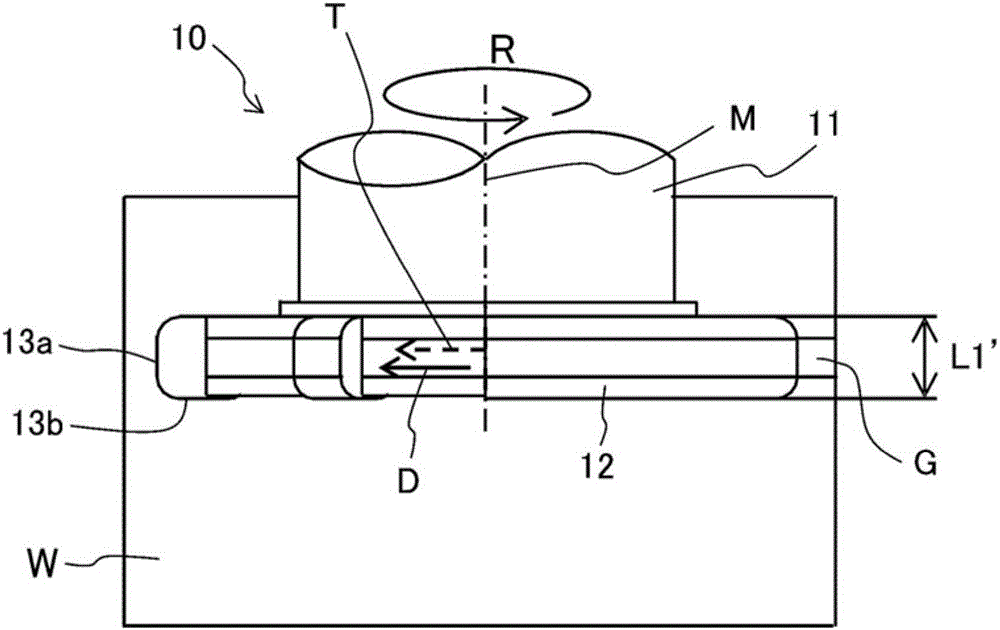
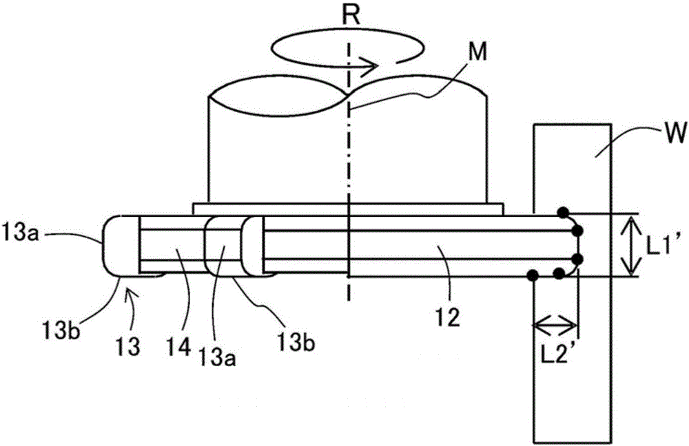
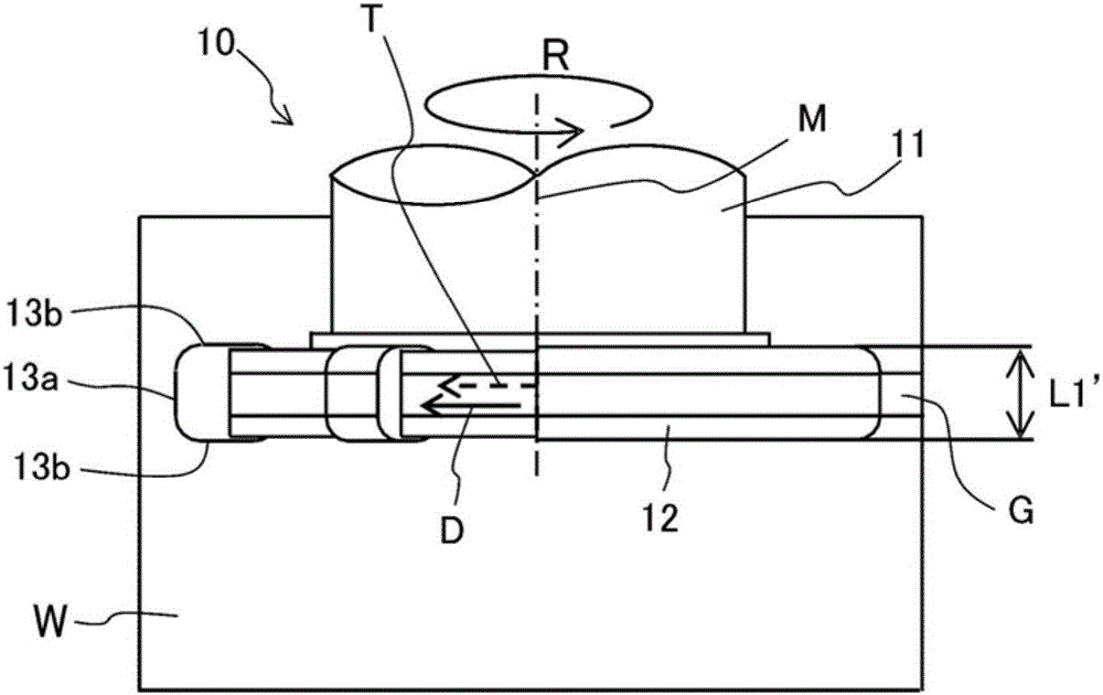
[0092] 4 is a schematic diagram showing a first embodiment of the method of processing a groove portion of the present invention using a single-cutting-edge type rotary tool, Figure 4A It is a diagram in which the relationship between the workpiece and the rotating tool is viewed from above with respect to the workpiece, Figure 4B It is viewed from the rear of the processing direction Figure 4A diagram of the relationship.

[0093] In addition, FIG. 5 is a schematic diagram showing a first embodiment of the groove portion processing method of the present invention using a double-sided cutting edge type rotary tool, Figure 5A It is a diagram in which the relationship between the workpiece and the rotating tool is viewed from above with respect to the workpiece, Figure 5B It is viewed from the rear of the processing direction Figure 5A diagram of the relationship.

[0094] In addition, in Fig. 4 and Fig. 5, all are the same as the case of Fig. 1 and Fig. 2, with respec...

no. 2 Embodiment

[0159] Next, a method of processing a groove portion according to a second embodiment of the present invention will be described with reference to FIG. 8 . Here, as an application example of the method of machining the groove portion, a case where a groove portion constituting a part of the gear shape is formed in a workpiece will be described.

[0160] 8 is a cross-sectional view showing an example of a processing sequence when a groove portion is formed by applying a groove portion processing method according to a second embodiment of the present invention, Figure 8A shows the general situation when the groove portion is processed to the first depth, Figure 8B shows the general situation when the groove is processed to the second depth, Figure 8C Shows the general situation when the groove is machined to the target machining depth, Figure 8D The general situation when the side surface and the bottom surface of the groove portion are processed is shown.

[0161] Here, ...


PUM


Abstract

The invention discloses a groove machining method. The method for forming a groove with a specified width and depth in a workpiece using a rotating tool that is provided with a disc-shaped tool body and multiple cutting edges at equal intervals on the outer circumferential surface of said tool body, the method being characterized in that with the rotation direction at the point of contact between the outer circumferential surface of the rotating tool and the workpiece inclined by a specified angle with respect to the direction of groove machining movement, said rotating tool is rotated while the outer circumferential surface thereof cuts into the machining surface of said workpiece by a specified cutting depth, after which said rotating tool is moved relative to the workpiece in the direction of groove machining movement.

Description

technical field [0001] The present invention relates to a method of forming a groove having a predetermined width and depth on a workpiece, and more particularly to a method of processing a groove on a workpiece using a rotary tool having a plurality of cutting edges on the side surface of a circular plate. Background technique [0002] There is known a technique for forming grooves on the surface of a workpiece, such as the grooves constituting the tooth surfaces of gears, using a milling cutter with a plurality of cutting edges mounted on the outer peripheral surface at equal intervals. The tool (gear milling tool) performs machining by relatively moving between the milling tool and the workpiece while cutting the cutting edge into the workpiece while rotating the milling tool (see Patent Document 1). [0003] The gear milling tool described in Patent Document 1 has, on both sides of the tool, a plurality of vertical blades arranged at equal intervals near the outer periph...

Claims


Application Information

Patent Timeline
Patent Type & Authority Applications(China)
IPC IPC(8): B23C3/28B23F5/20
CPCB23C3/28B23C2220/605B23F5/20B23F15/00B23F21/12B23F5/163B23F21/143B23C1/12B23C3/30B23C2220/36B23Q27/003
Inventor 北山稔伊藤博山本雄记
Owner YAMAZAKI MAZAK KK
Learn More