Eureka AIR delivers breakthrough ideas for toughest innovation challenges, trusted by R&D personnel around the world.

Multifunctional cooking device

A cooking device and multi-functional technology, applied in the field of kitchen appliances, can solve the problems of lower consumer acceptance and insufficient applicability of electromagnetic heating devices, and achieve the effects of ensuring electromagnetic heating efficiency, improving utilization rate, and avoiding falling off

Inactive Publication Date: 2017-05-10
JOYOUNG CO LTD
View PDF7 Cites 0 Cited by
  • Summary
  • Abstract
  • Description
  • Claims
  • Application Information

AI Technical Summary

Problems solved by technology

If other utensils or pots in the consumer's home do not have magnetic conductivity, the applicability of the electromagnetic heating device is insufficient, which reduces the consumer's acceptance

Method used


Image

  • Multifunctional cooking device
  • Multifunctional cooking device
  • Multifunctional cooking device

Examples


no. 1 approach

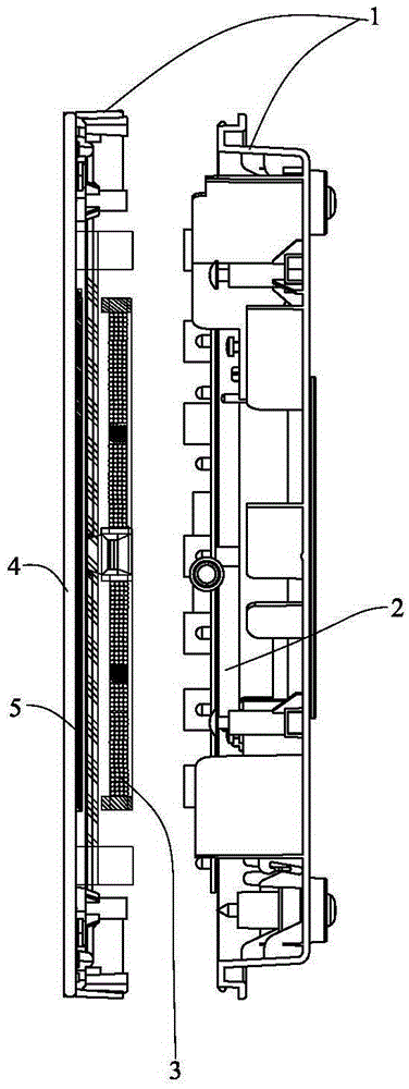
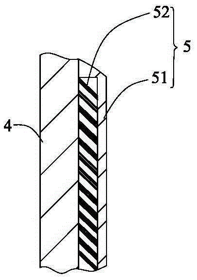
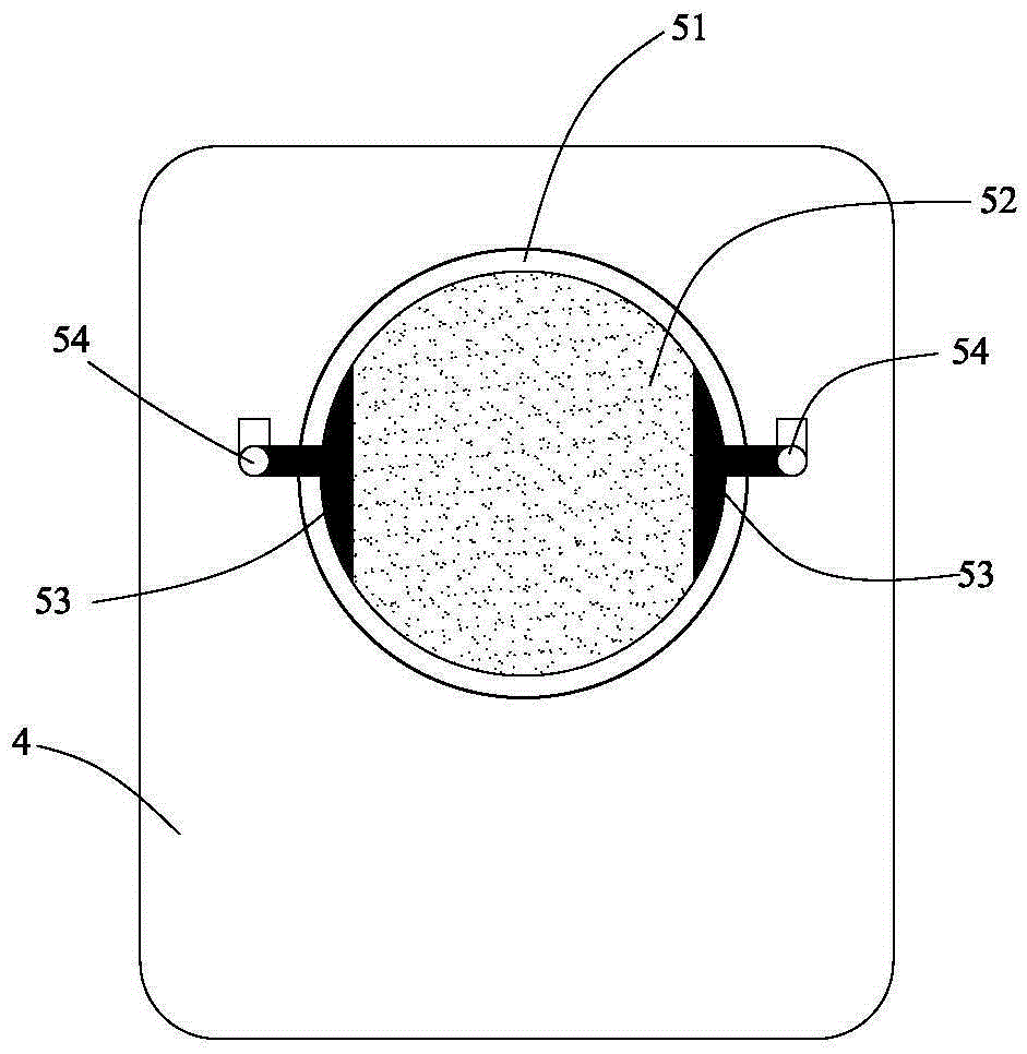
[0033] see figure 1 , figure 2 Shown is the first embodiment of a multifunctional cooking device of the present invention, which is an induction cooker, including a housing 1, a control circuit board 2 located in the housing 1, and a magnetic wire reel 3, and the electromagnetic wire reel 3 is electrically connected to the control circuit board 2. The control circuit board includes a pot detection unit (not shown) and a heating control unit (not shown). The housing is provided with a panel 4 for heat penetration, and the panel 4 is provided with a non-metallic electric heating film 5, the electric heating film 5 is set corresponding to the heating area of ​​the electromagnetic coil 3, and the electric heating film 5 is electrically heated. Connected to the control circuit board, the heating control unit controls the electric heating film 5 and the electromagnetic coil 3 to work independently of each other according to the signal of the pan detection unit.

[0034] In this e...

Embodiment approach 2

[0048] see Figure 5 The shown second embodiment of a multifunctional cooking device of the present invention is different from the first embodiment in that: a heat insulating layer 6 is provided between the electric heating film 5 and the electromagnetic wire disk 3 . Effectively avoid mutual heat radiation between the electric heating film 5 and the electromagnetic coil 3, greatly improving reliability and lifespan. And greatly improve the heating energy efficiency.

[0049] In this embodiment, the heat insulation layer 6 is arranged inside the panel 4 together with the electric heating film 5 , covers the outside of the insulating layer 51 of the electric heating film 5 , and seals the electric heating film inside. In this way, internal space can be saved.

[0050] In this embodiment, the heat insulation layer 6 is made of asbestos or asbestos mixture or mica material with high temperature heat insulation effect.

[0051] As an improvement, a first heat dissipation gap i...


PUM


Abstract

The invention relates to a multifunctional cooking device, and the device comprises a housing, a control circuit board and an electromagnetic wire coil, wherein the control circuit board and the electromagnetic wire coil are located in the housing. The electromagnetic wire coil is electrically connected with the control circuit board, and the control circuit board comprises a pan detection unit and a heating control unit. The housing is provided with a panel which allows heat to pass. The panel is provided with an electric heating film which allows the magnetic field of the electromagnetic wire coil to pass, and the electric heating film is set to be corresponding to a heating region of the electromagnetic wire coil. The electric heating film is electrically connected with the control circuit board. The heating control unit sequentially controls the electric heating film and the electromagnetic wire coil to work independently through signals of the pan detection unit. Therefore, a user can place any type of pans on the device to cook food, thereby greatly improving the adaptability of an electromagnetic heating device, and changing the dependence of electromagnetic heating products on the pans.

Description

technical field [0001] The invention relates to the field of kitchen appliances, in particular to a cooking device with multiple functions. Background technique [0002] Due to its high thermal efficiency, electromagnetic heating has been widely used in kitchen appliances such as induction cookers, stoves, and electric hot pots. However, the current electromagnetic heating technology is only suitable for appliances made of magnetic materials, such as iron and stainless steel. In order to improve the adaptability of electromagnetic heating, people have produced technologies such as adding magnetically permeable films or composite negatives on non-magnetic appliances, expanding the scope of application of electromagnetic heating technology. [0003] But the above-mentioned technology is also based on the change of the utensil itself, relying on the use of the magnetic permeable material on the utensil. If other utensils or other pots in the consumer's home do not have magneti...

Claims


Application Information

Patent Timeline
IPC IPC(8): H05B6/02
Inventor 朱泽春胡文飞钟启华
Owner JOYOUNG CO LTD
Why Eureka
Eureka Blog
Learn More