Measurement system

A measurement system and the technology of the tested part, which is applied in the field of communication, can solve the problems of long measurement time, inability to simulate the vacuum environment with infinity and extremely low reflection, and impurity in the microwave anechoic chamber.

Active Publication Date: 2017-05-10
GENERAL TEST SYST
View PDF6 Cites 3 Cited by
  • Summary
  • Abstract
  • Description
  • Claims
  • Application Information

AI Technical Summary

Problems solved by technology

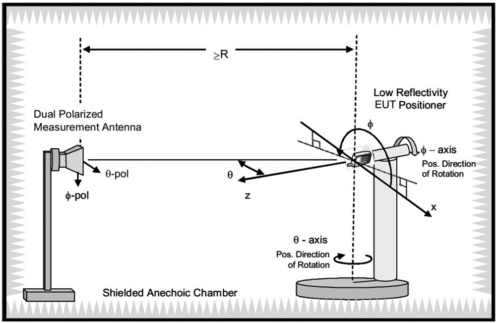
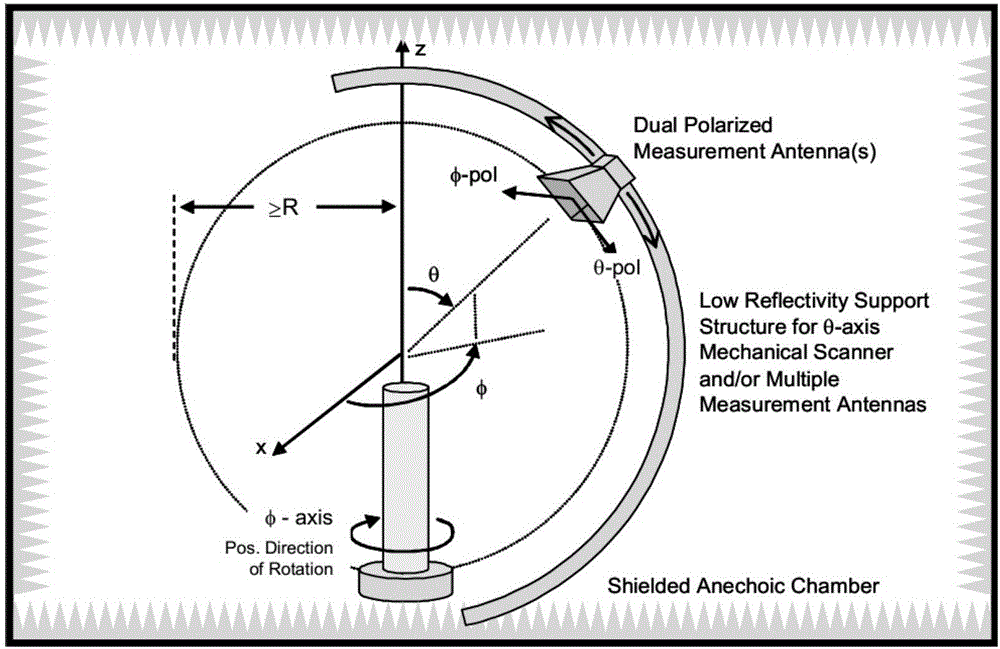
However, this type of measurement system has the following defects: (1) the measurement speed is slow and the measurement time is long; (2) figure 1 The 3D turntable system in and figure 2 The rotating structure of the antenna loop in the anechoic chamber will increase the difficulty of designing and constructing the anechoic chamber; (3) more importantly, these mechanical devices placed inside the anechoic chamber will increase the reflection of electromagnetic waves inside the anechoic chamber, and the reflected electromagnetic wave is equivalent to noise for measurement , causing the microwave anechoic chamber to be impure and unable to simulate the vacuum environment of infinity and extremely low reflection, resulting in the inaccuracy of wireless device performance measurement
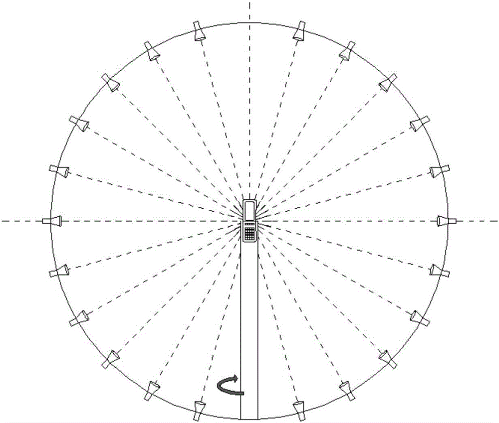
This type of measurement system has a fast measurement speed and a short measurement time period, but there are still defects: (1) When the darkroom space is not large enough, setting multiple measurement antennas on the same plane will cause the distance between the antennas to be small, that is, the distance between the antennas The isolation is not enough, and the coupling interference between adjacent antennas will cause measurement errors; (2) Since the measurement antenna itself is also a signal transmission source, it is a conductive medium existing inside the dark room. When one measurement antenna is transmitting measurement signals, other antennas Can be considered as reflection source
Therefore, in a system with multiple measurement antennas, there is a reflection source within a small angle range directly in front of any measurement antenna, which will increase the reflection of the dark room and also lead to inaccurate measurement

Method used


Image

  • Measurement system
  • Measurement system
  • Measurement system

Examples


Embodiment 1

[0056] The distribution of the measurement antenna in Example 1 is as Figure 5a , Figure 5b and Figure 5c As shown, 11 measuring antennas are distributed on two mutually perpendicular planes, among which, 5 measuring antennas 101 are distributed on the same plane, 6 measuring antennas 102 are distributed on the same plane, and the coordinates of the 11 measuring antennas are A 1 (ρ, 15°, 0°), A 2 (ρ, 30°, 90°), A 3 (ρ, 45°, 0°), A 4 (ρ, 60°, 90°), A 5 (ρ, 75°, 180°), A 6 (ρ, 90°, 90°), A 7 (ρ, 105°, 180°), A 8 (ρ, 120°, 90°), A 9 (ρ, 135°, 0°), A 10 (ρ, 150°, 90°), A 11 (ρ, 165°, 0°). Among the included angles formed by any two measuring antennas and the origin, the range of the included angle α with the origin as the vertex is 30°≤α≤150°.

Embodiment 2

[0057] The distribution of the measurement antenna in embodiment 2 is as Figure 6a , Figure 6b and Figure 6c As shown, 11 measuring antennas are distributed on two mutually perpendicular planes, among which, 5 measuring antennas 201 are distributed on the same plane, 6 measuring antennas 202 are distributed on the same plane, and the distribution of 11 measuring antennas is A 1 (ρ, 15°, 0°), A 2 (ρ, 30°, 90°), A 3 (ρ, 45°, 0°), A 4 (ρ, 60°, 90°), A 5 (ρ, 75°, 0°), A 6 (ρ, 90°, 90°), A 7 (ρ, 105°, 0°), A 8 (ρ, 120°, 90°), A 9 (ρ, 135°, 0°), A 10 (ρ, 150°, 90°), A 11 (ρ, 165°, 0°). Among the included angles formed by any two measuring antennas and the origin, the range of the included angle α with the origin as the vertex is 30°≤α≤150°.

Embodiment 3

[0058] The distribution of the measurement antenna in embodiment 3 is as Figure 7a , Figure 7b and Figure 7c As shown, 11 measuring antennas are distributed on two mutually perpendicular planes, among which, 6 measuring antennas 301 are distributed on the same plane, 5 measuring antennas 302 are distributed on the same plane, and the distribution of 11 measuring antennas is A 1 (ρ, 15°, 90°), A 2 (ρ, 30°, 270°), A 3 (ρ, 45°, 180°), A 4 (ρ, 60°, 90°), A 5 (ρ, 75°, 0°), A 6 (ρ, 90°, 270°), A 7 (ρ, 105°, 90°), A 8 (ρ, 120°, 180°), A 9 (ρ, 135°, 270°), A 10 (ρ, 150°, 0°), A 11 (ρ, 165°, 180°). Among the included angles formed by any two measuring antennas and the origin, the range of the included angle α with the origin as the vertex is 30°≤α≤165°.


PUM


Abstract

The invention discloses a measurement system. The system comprises an anechoic chamber, a rotary table, N measurement antennas (N is natural number and not less than 11); a spherical surface coordinate system is established by taking the center of a measured part as an original point; the distribution of the measurement antennas is as shown in description, wherein thetai is the positive integral multiple of 15 DEG, and at least comprises a measurement antenna at each of the theta angle of 15 DEG, 30 DEG, 45 DEG, 60 DEG, 75 DEG, 90 DEG, 105 DEG, 120 DEG, 135 DEG, 150 DEG and 165 DEG; as shown in description, and N measurement antennas are not on the same plane. The system disclosed by the invention can create a measurement environment with small coupling interference among the measurement antennas and low reflection in the small anechoic chamber, thereby improving the measurement precision.

Description

Technical field [0001] The present invention relates to the field of communications, and in particular, to a system for wireless performance parameter measurement. Background technique [0002] According to the International Standards Organization CTIA (Mobile Communications Network Association) standard, the wireless performance measurement of antennas and wireless devices needs to be measured on a spherical surface with the measured object as the center of the sphere, and all the measurement results are measured at different spatial positions. The corresponding index is obtained by comprehensive calculation, and the measurement index of the wireless terminal can be registered to the network after meeting the requirements. In order to ensure the accuracy of the measurement, the measurement needs to be performed in an anechoic chamber to eliminate noise interference from the external environment. The white paper issued by CTIA has extremely strict requirements on the darkroom me...

Claims


Application Information

Patent Timeline
IPC IPC(8): H04B17/10H04B17/20H04B17/345
CPCH04B17/101H04B17/20H04B17/345G01R29/105G01R29/0821H04B17/29H04B17/15
Inventor 罗庆春沈鹏辉于伟
Owner GENERAL TEST SYST
Why Eureka
Try Eureka