
Electrical conduit connecting bend

A technology of electrical bushings and connecting elbows, applied in the direction of cable joints, etc., can solve the problems of wire insulator damage, inability to adjust, unfavorable protection of wire insulators, etc., to reduce stress, improve protection, and increase buffering effects Effect

Active Publication Date: 2017-05-10
河北万力高强度紧固件制造有限公司
View PDF8 Cites 2 Cited by
  • Summary
  • Abstract
  • Description
  • Claims
  • Application Information

AI Technical Summary

Problems solved by technology

[0003] In the actual use of electrical bushings, because their length often cannot meet the requirements of use, in most cases it needs to be cut and connected. Two types, one is to cut the two electrical casings to be connected into the same matching angle, and then use PVC adhesive for bonding, and the other is to connect by adding arc-shaped connectors; in the above Under the two connection methods, the first one generally has a sharper connection angle at the connection, which is likely to cause damage to the wire insulator during use of the electrical bushing, while the angle of the arc connector is basically the same during use. It is fixed and cannot be adjusted, and the wires in the existing arc-shaped connectors are basically pulled in the form of sliding friction after they penetrate, without using the insulator to protect the wire itself. In view of this, the present invention provides an electrical bushing Connecting elbows, the specific friendship effects are as follows:

Method used


Image

  • Electrical conduit connecting bend
  • Electrical conduit connecting bend
  • Electrical conduit connecting bend

Examples


Embodiment Construction

[0022] In order to make the technical means, creative features, goals and effects achieved by the present invention easy to understand, the present invention will be further described below in conjunction with specific embodiments.

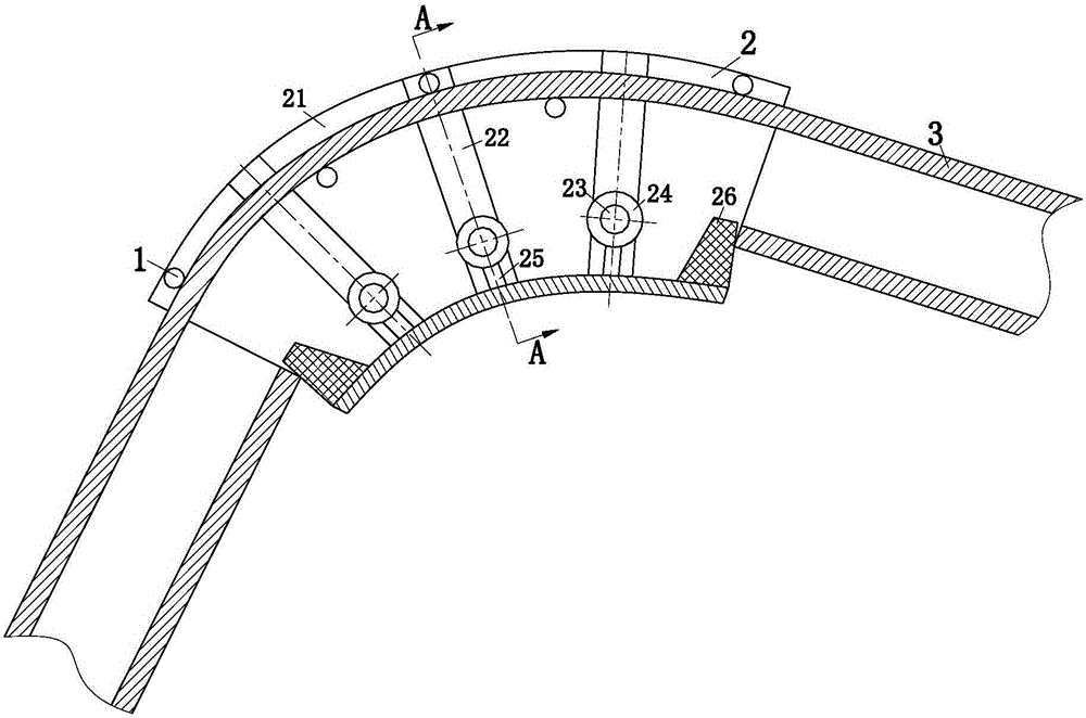
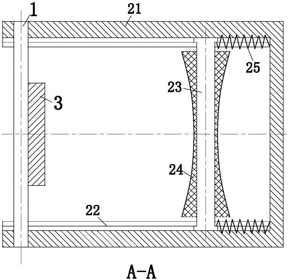
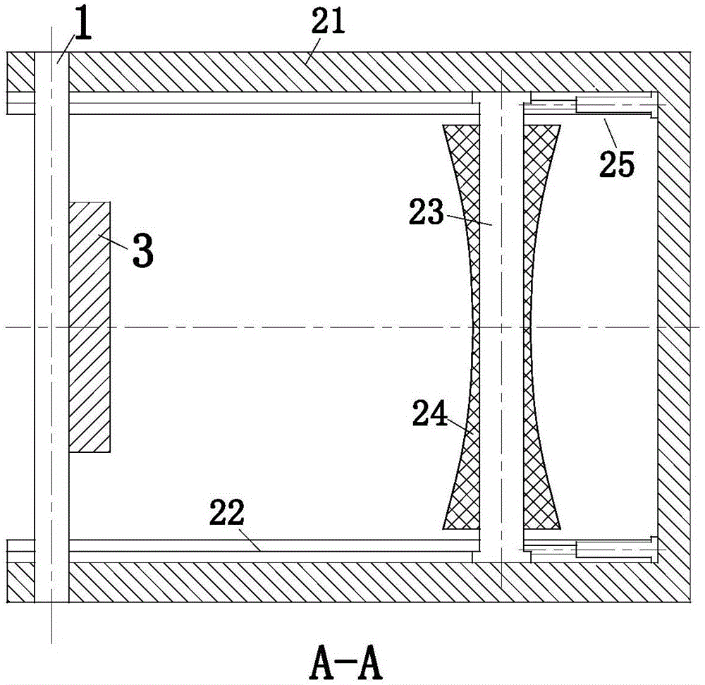
[0023] Such as Figure 1 to Figure 4 As shown, an electrical bushing connection elbow according to the present invention includes a positioning unit 1 and a joint unit 2, the joint unit 2 is connected to the electrical bushing 3, and the connection between the electrical bushing 3 and the joint unit 2 The positioning unit 1 is used for positioning. The connecting unit 2 is mainly used to protect the wires at the joint of the electrical bushing. The positioning unit 1 is used to fix the position of the connecting unit 2 and the electrical bushing 3, thereby facilitating the pairing of the connecting unit 3. The electric wires in the electrical sleeve 3 produce protection.

[0024] Such as Figure 1 to Figure 4 As shown, a kind of electrical bushi...


PUM


Abstract

The invention relates to the field of circuit arrangement tools, in particular to an electrical conduit connecting bend. The connecting bend comprises a locating unit and a connecting unit, wherein the connecting unit is connected with an electrical conduit; the electrical conduit and the connecting unit are located through the locating unit; the connecting unit is mainly used for realizing a protective effect of an electrical wire at the joint of the electrical conduit; and the locating unit is used for performing position fixing on the connecting unit and the electrical conduit, so that the connecting unit generates the protective effect for the electrical wire in the electrical conduit. The connecting bend is mainly suitable for connection of the electrical conduit needed to be cut; a roller wheel is arranged in the bend, so that frictional force between the existing bend and the electrical wire can be converted to be in a rolling friction form from a sliding friction form; and in combination with the design of an elastic component, the stress effect of the electrical wire at the corner in the electrical conduit can be reduced, so that the protective effect of the connecting bend on the electrical wire in a using process can be improved.

Description

technical field [0001] The invention relates to the field of circuit layout tools, in particular to an electrical bushing connecting elbow. Background technique [0002] Electrical bushing is a protective product for building electrical safety. Currently, PVC resin is used as the main raw material, and an appropriate amount of additives are added. It is processed by mixing, extrusion, sizing, cooling and other processes. The use method of electrical casing is generally two steps: 1. Cutting the pipe. It is convenient to cut the pipe with professional scissors. First, open the scissors, put the pipe on the edge of the knife, and hold the handle of the scissors tightly so that the gear locks the edge of the knife. , then release the handle, and then hold it tightly repeatedly until the pipe is cut off. This makes the incision complete, avoiding damage to the insulator of the wire when the wire is threaded. It is also possible to cut the pipe with a bow saw, but the incision n...

Claims


Application Information

Patent Timeline
IPC IPC(8): H02G15/18
CPCH02G15/18
Inventor 李霞林
Owner 河北万力高强度紧固件制造有限公司
Learn More