Jump catch clamp, integrated tool for jump catch riveting and flanging and machining method thereof
An integrated, snap-off technology, applied in emergency protection devices, emergency protection device manufacturing, electrical components, etc., can solve problems affecting product quality, low processing efficiency, product deformation, etc., to ensure the quality of riveting and flanging, installation Quick, easy-to-place effects
- Summary
- Abstract
- Description
- Claims
- Application Information
AI Technical Summary
Problems solved by technology
Method used
Image
Examples
Embodiment 1
[0046] combine Figure 5 , a jumper fixture in this embodiment, including a drawer seat 81 and a pull rod 82, the draw rod 82 is connected to one end of the drawer seat 81, and the drawer rod 82 is used to push the drawer seat 81 into and out of the tooling . Along the length direction of the drawer seat 81, at least one jumper placement station is arranged, and the jumper placement station is used for initial assembly of each part of the jumper before the parts of the jumper are not riveted. This embodiment is designed to set a plurality of snap button placement stations along the length direction of the drawer seat 81. Compared with the traditional staff, the jump button workpiece is manually clamped in 4 times, and the riveting and flanging process of the jump button is completed in 4 times. That is to say, the assembly of multiple snap buttons can be completed, and the processing efficiency is doubled, which also reduces the labor intensity of the staff and liberates prod...
Embodiment 2
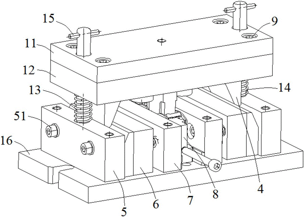
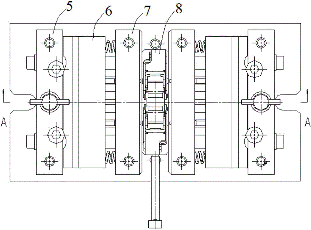
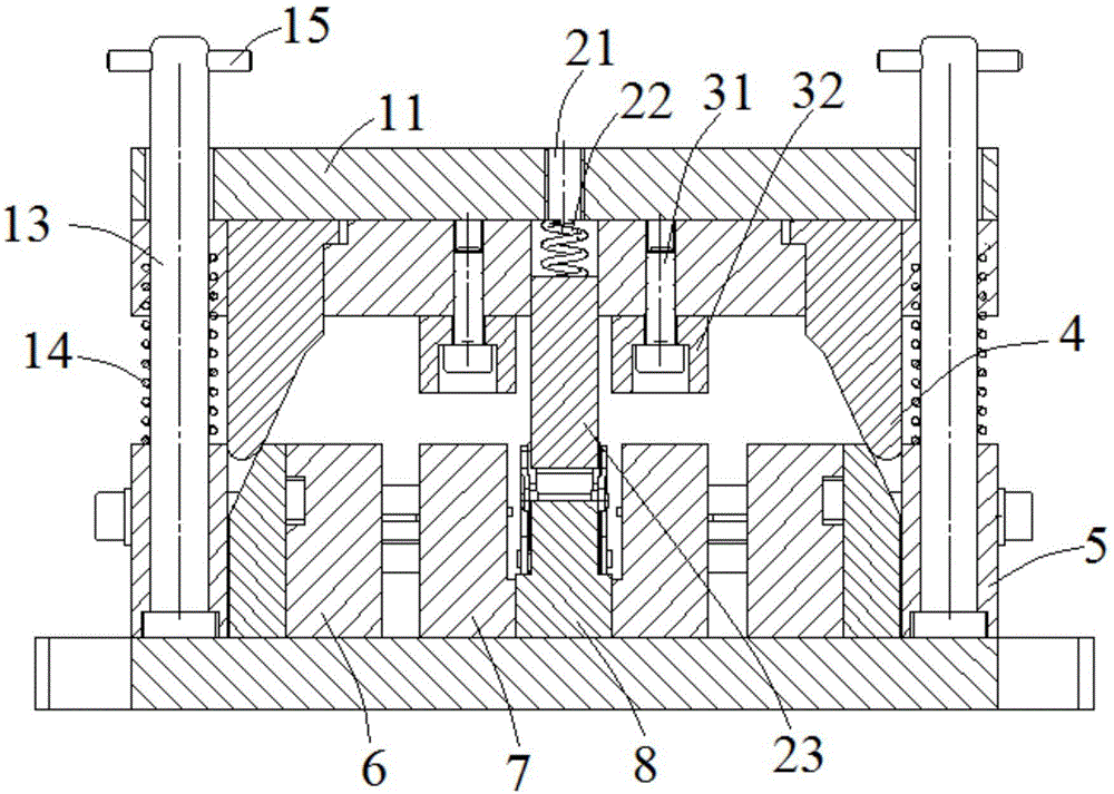
[0050] combine figure 1 , figure 2 and image 3 , a jump button riveting and flanging integrated tooling of this embodiment, including an upper die, a guide post 13, a guide post spring 14, a bottom plate 16, a first lower die column plate 5, a slider assembly 6, and a second lower die Column plate 7 and jumper clip 8 described in Embodiment 1. Wherein, the upper mold includes an upper baffle plate 11 and an upper mold fixed plate 12, and the upper baffle plate 11 and the upper mold fixed plate 12 are connected by fixing pins 9, and the guide post 13 is connected in series with the upper mold and the first lower mold column plate 5 And the bottom plate 16, the end of the guide post 13 passing through the upper baffle plate 11 is horizontally inserted into the limit pin 15, and the limit pin 15 is used to limit the upward position of the upper mold. The guide post spring 14 is passed through the guide post 13, and the guide post spring 14 is used to help the upper die retu...
Embodiment 3
[0063] The snap-off fixture of this embodiment is basically the same as that of Embodiment 1; the integrated tooling of the snap-off riveting and flanging is basically the same as that of Embodiment 2, the difference being that the snap-off fixture of this embodiment is set along the length direction of the drawer seat 81 There are four jumper placement stations, and 4 jumper placement stations are set in pairs. Correspondingly, the punch layout of the slider assembly 6 and the column plate 7 of the second lower die in the one-piece tooling for jumper riveting and flanging are also adaptively changed.
[0064]The jumper clamp, jumper riveting and flanging integrated tooling described in Examples 1-3 adopts an integrated modular design and can be installed on different presses or desktop punching machines, which is convenient for production scheduling and easy to operate, making the jumper One-time assembly is completed, riveting and flanging are of reliable quality, and the to...
PUM
 Abstract
Description
Claims
Application Information
 - R&D
- Intellectual Property
- Life Sciences
- Materials
- Tech Scout
- Unparalleled Data Quality
- Higher Quality Content
- 60% Fewer Hallucinations
Browse by: Latest US Patents, China's latest patents, Technical Efficacy Thesaurus, Application Domain, Technology Topic, Popular Technical Reports.
© 2025 PatSnap. All rights reserved.Legal|Privacy policy|Modern Slavery Act Transparency Statement|Sitemap|About US| Contact US: help@patsnap.com


