Minimum spacing controllable ultra-wideband grating lobe-free sparse array design method

A design method and ultra-wideband technology, applied in antenna arrays, antennas, computing and other directions, can solve problems such as inability to meet, reduce peak side lobe levels, low peak side lobe levels, etc., and achieve the effect of controllable minimum spacing

Inactive Publication Date: 2017-05-10
XIAMEN UNIV +1
View PDF5 Cites 8 Cited by
  • Summary
  • Abstract
  • Description
  • Claims
  • Application Information

AI Technical Summary

Problems solved by technology

[0003] There are many studies on sparse arrays. In literature [6], a method based on convex optimization is proposed to achieve array sparseness. The two optimization goals are to minimize the peak sidelobe level and maximize the sparsity. Compared with the array element The same number of uniform linear arrays, the sparse linear array has lower peak sidelobe levels and narrower main lobe width, but this method does not address wideband performance
Chinese patent CN201410419309.4 discloses a method for quickly realizing low sidelobe combined with array antenna radiation field and scattering field[7]. The patent first optimizes the uniform array to obtain the initial sparse arrangement scheme, and then calculates and compares the radiation field of the array antenna and the maximum sidelobe level of the scattering field. When the low sidelobe requirements are met at the same time, the optimization result will be obtained. Otherwise, the array antenna sparse arrangement matrix is ​​updated by the method of crossover and mutation. The disadvantage of this patent is that it does not involve broadband performance. The array has problems with grating lobes when operating in the UWB frequency range
However, the peak sidelobe / grating lobe level of the UWB array obtained by this method with a minimum spacing greater than half the wavelength of the low frequency of 101 elements or below is only about -10db, which cannot meet the needs of general engineering applications

Method used


Image

  • Minimum spacing controllable ultra-wideband grating lobe-free sparse array design method
  • Minimum spacing controllable ultra-wideband grating lobe-free sparse array design method
  • Minimum spacing controllable ultra-wideband grating lobe-free sparse array design method

Examples


Embodiment Construction

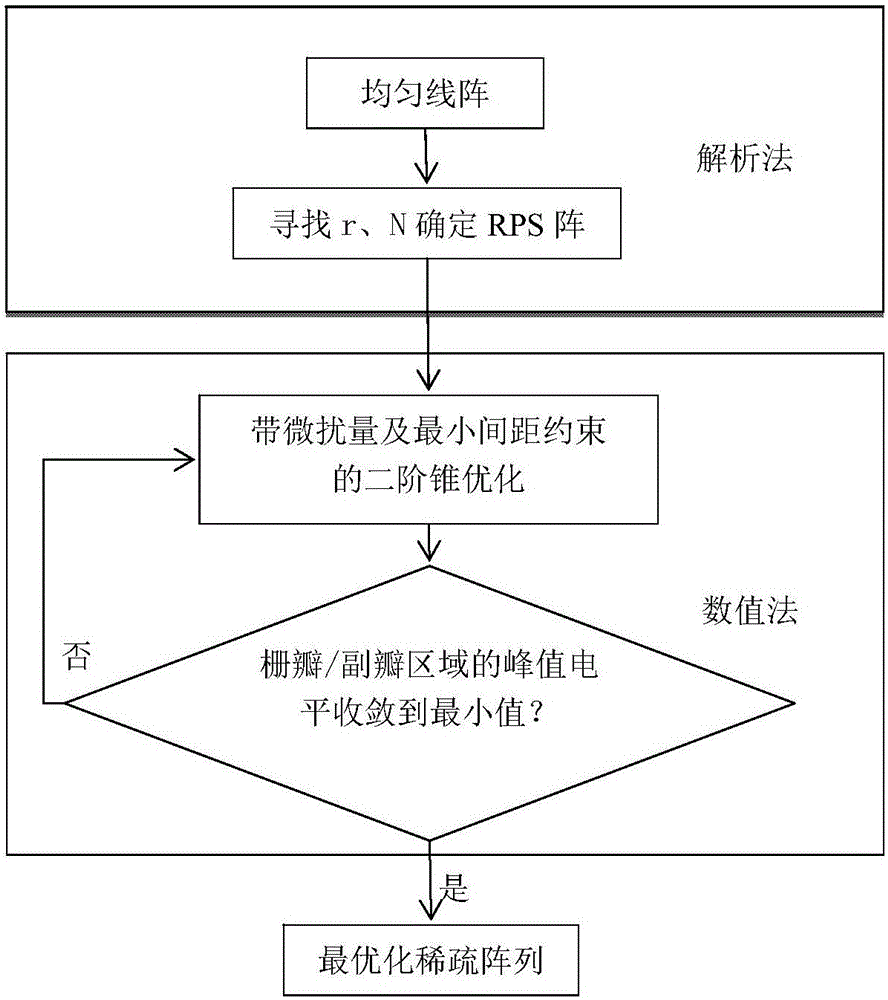
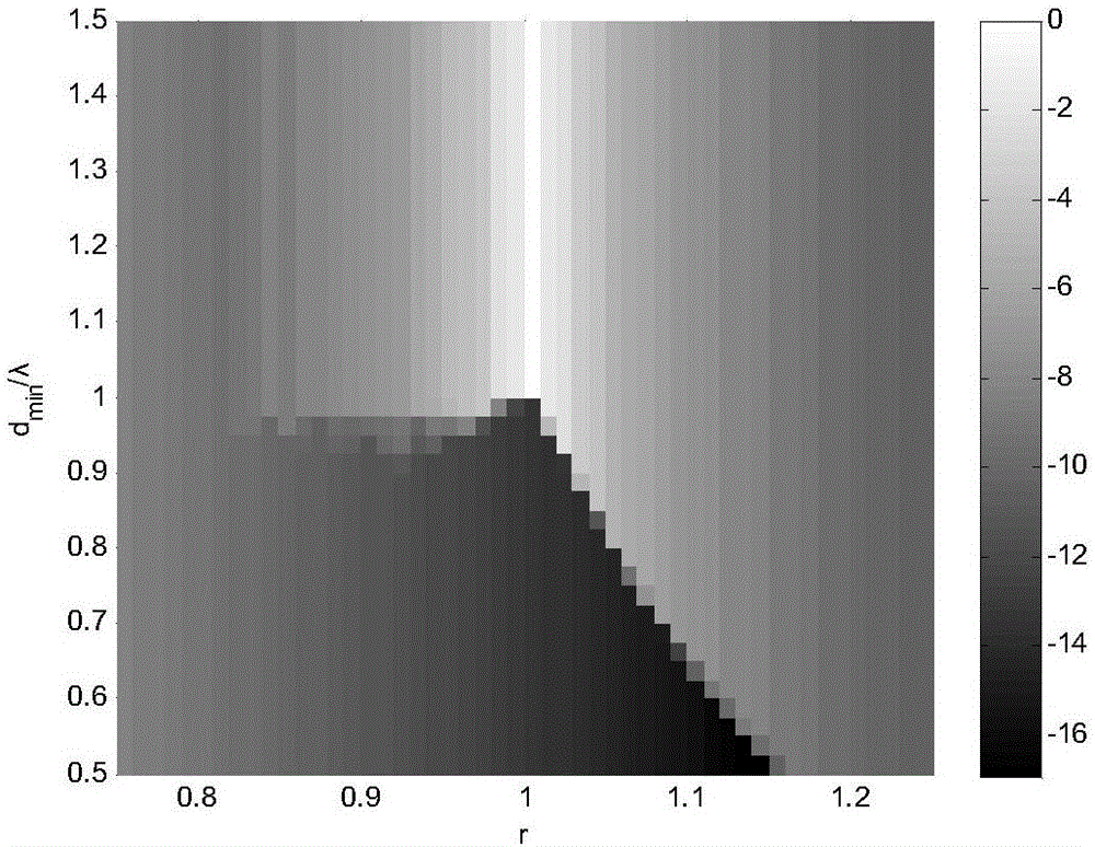
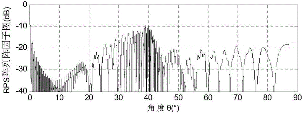
[0066] The design method of the ultra-broadband grating-lobe sparse linear array with controllable minimum spacing proposed by the present invention is divided into two steps, such as figure 1 Shown: In the first step, the RPS array designed by the analytical method determines the ultra-wideband sparse linear array; in the second step, the multi-step numerical perturbation optimizes the position of the array elements of the above array to obtain a lower grating lobe / peak sidelobe level Ultra-wideband sparse line array with controllable minimum spacing. figure 1 It is a technical flow chart of the present invention.

[0067] Below in conjunction with an example the present invention is further explained. Design goal: an ultra-wideband grating-lobe-free sparse linear array with a frequency range between 1GHz and 3GHz, and the peak level of the grating lobe / sidelobe area remains unchanged.

[0068] Follow the steps below to implement:

[0069] Step 1: Assume that a wide-band a...


PUM


Abstract

The invention discloses a minimum spacing controllable ultra-wideband grating lobe-free sparse array design method, and relates to an antenna. The method comprises the steps that a minimum spacing controllable ultra-wideband grating lobe-free sparse array is provided, and a low peak side lobe level is achieved; on the premise that the peak level of a grating lobe / side lobe area inside an wide band basically remains unchanged, the peak level of the grating lobe / side lobe area can be reduced to the maximum extent; compared with some algorithms such as a genetic algorithm, the minimum spacing controllable ultra-wideband grating lobe-free sparse array design method with the speed obviously increased is optimized on the basis of an iterative convex optimized numerical perturbation optimization method. According to the basic idea, firstly, an ultra-wideband sparse array is designed through an analytical method; then, the RPS array designed through the analytical method is further optimized through multistep position perturbation, and then the peak level of the grating lobe / side lobe area is greatly reduced. In the whole optimization layout process, the minimum spacing is controllable all the time.

Description

technical field [0001] The invention relates to antennas, in particular to a design method for ultra-broadband sparse line arrays without grating lobes and controllable minimum spacing. Background technique [0002] With the rapid development of electronic technology and the emergence of broadband communication equipment, the ultra-wideband technology of antennas is also constantly developing. Ultra-wideband antennas can realize instantaneous reception of broadband signals, and can be shared by different functional systems, and have a wide range of applications in communication, navigation, and radar [1,2]. There are different definitions of ultra-wideband in different applications, and the definition of ultra-wideband in the present invention means that the bandwidth ratio in the frequency domain is not less than 3:1. Sparse array means that the positions of the array elements are no longer evenly distributed at half-wavelength equal intervals, but are distributed at unequ...

Claims


Application Information

Patent Timeline
IPC IPC(8): G06F19/00H01Q21/00
CPCG16Z99/00H01Q21/00
Inventor 刘颜回杨雨琦张正鸿张浩斌王亮刘洋唐益民
Owner XIAMEN UNIV
Why Eureka
Try Eureka