
Constant current switching power supply and its constant current controller

A flow controller and switch circuit technology, applied in control/regulation systems, DC power input conversion to DC power output, instruments, etc., can solve the problem of large peak level of electromagnetic interference, unfavorable EMI filter design, and increase system EMI filtering To reduce the peak level, reduce the design cost and maintain high precision

Active Publication Date: 2016-03-02
FREMONT MICRO DEVICES SHENZHEN LTD
View PDF5 Cites 0 Cited by
  • Summary
  • Abstract
  • Description
  • Claims
  • Application Information

AI Technical Summary

Problems solved by technology

[0003] However, the peak level of electromagnetic interference in the circuit is related to the switching frequency of the constant current controller. When the switching frequency of the constant current controller is fixed, the peak level of electromagnetic interference is relatively large, which is not conducive to the EMI filter design, which increases the design cost of the system EMI filter

Method used


Image

  • Constant current switching power supply and its constant current controller
  • Constant current switching power supply and its constant current controller
  • Constant current switching power supply and its constant current controller

Examples


Embodiment Construction

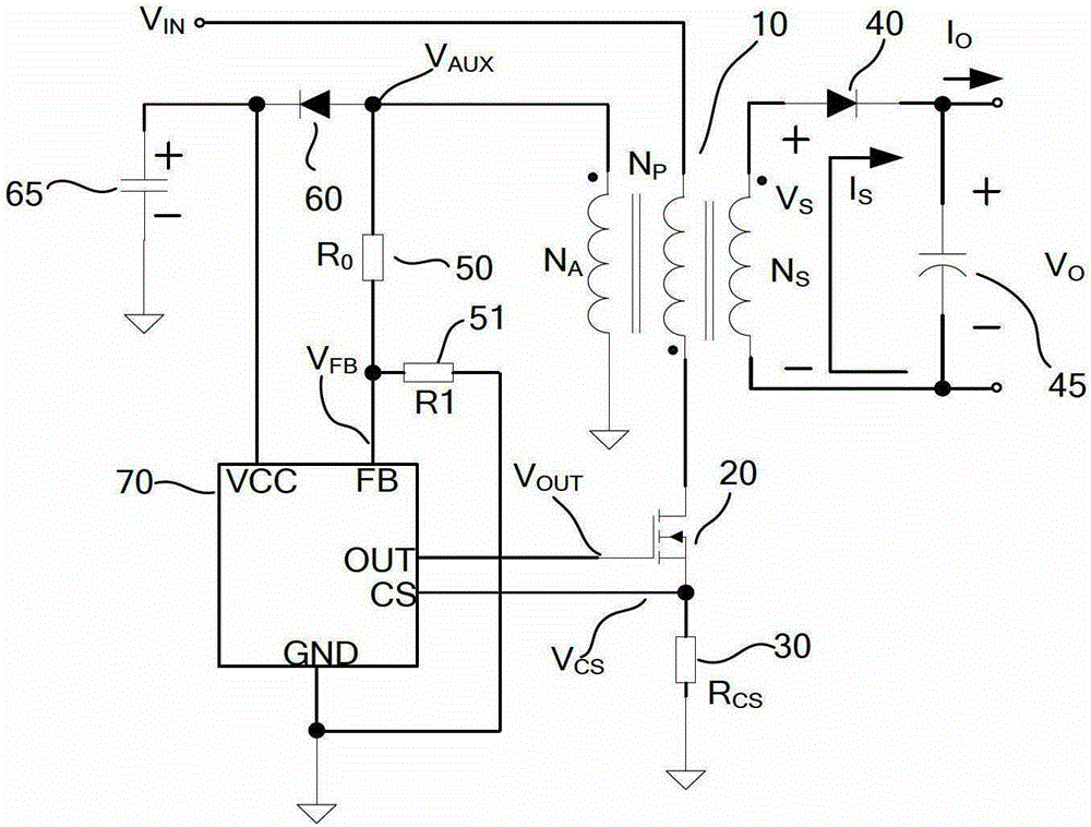
[0030] image 3 It is the circuit schematic diagram of the constant current switching power supply of the present invention. Such as image 3 As shown, the constant current switching power supply of the present invention includes a transformer 10, a voltage divider circuit connected between the first input terminal and the second input terminal of the primary side of the transformer 10, a main switching tube 20, an output circuit and a constant current controller 70 . The voltage dividing circuit includes a resistor R0 and a resistor R1. Wherein, the resistor R0 and the resistor R1 are connected in series between the first input terminal and the second input terminal of the primary side of the transformer. The power supply terminal VCC of the constant current controller 70 is connected to the first input terminal of the primary side of the transformer 10 . The feedback control terminal FB of the constant current controller 70 is connected to the voltage dividing point of t...


PUM


Abstract

The invention relates to a constant current switching power supply and a constant current controller of the constant current switching power supply. The constant current controller comprises a FB waveform detecting module, a triangular wave generating module, a waveform control module and an output module, wherein the FB waveform detecting module, the triangular wave generating module, the waveform control module and the output module are connected in sequence. The waveform control module is used for receiving triangular waves output by the triangular wave generating module and for controlling output voltage waveforms of the output module according to triangular wave output control signals, so that the output voltage waveforms of the output module have periodic variation, moreover each period comprises a plurality of pulses, and the interval between any two adjacent pulses is unequal to others. The constant current switching power supply comprises a transformer, a voltage division circuit, a main switch tube, an output circuit and the constant current controller. The constant current switching power supply and the constant current controller can achieve switch frequency jittering, are conducive to reduction of the peak level of electromagnetic interference and to reduction of design cost of a system EMI filter, and meanwhile maintain high-precision constant current output.

Description

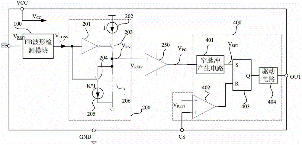
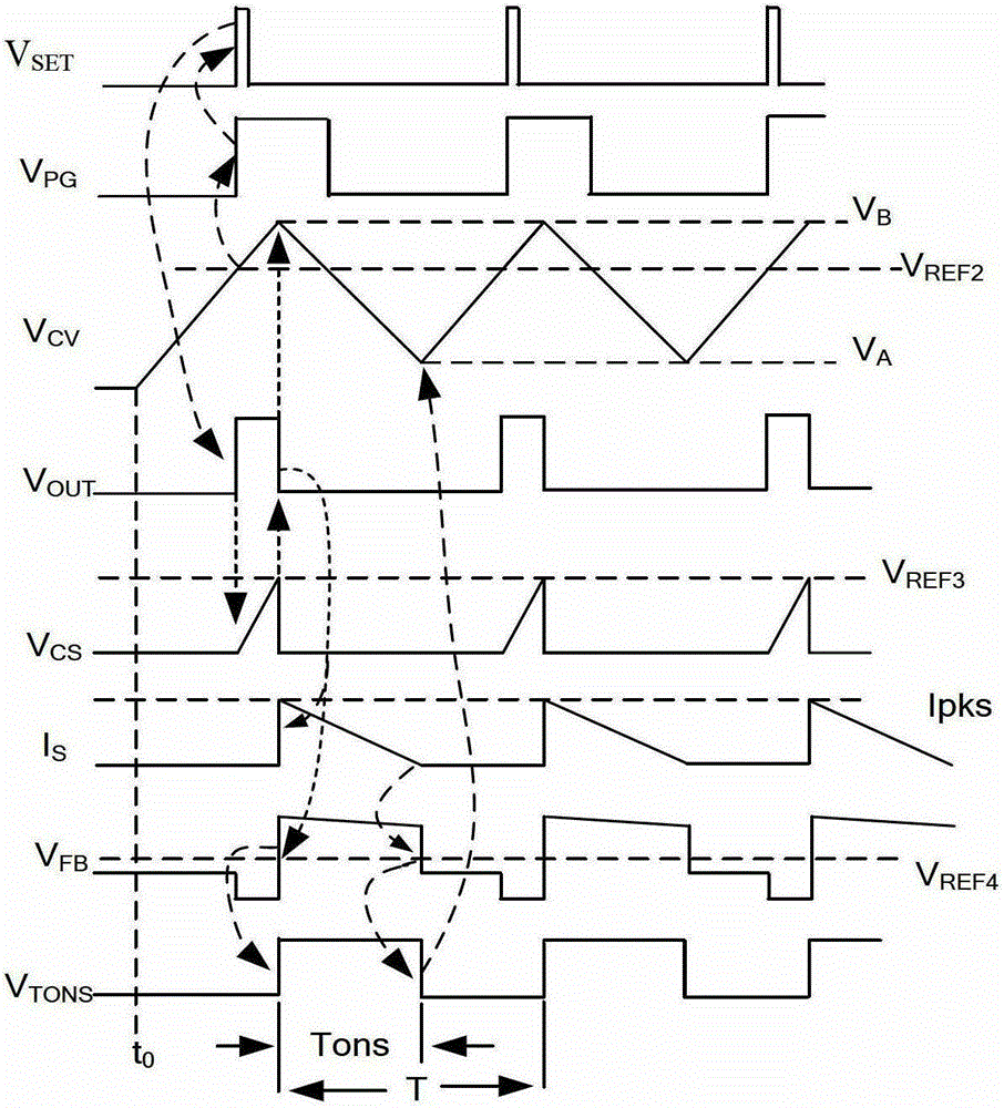
technical field [0001] The invention relates to the field of switching power supplies, more specifically, to a constant current switching power supply and a constant current controller thereof. Background technique [0002] figure 1 It is a schematic circuit diagram of a constant current controller in PFM mode in the prior art. Such as figure 1 As shown, the existing constant current controller in PFM mode includes an FB waveform detection module 100 , a triangular wave generation module 200 , a comparator 250 and an output module 400 connected in sequence. figure 2 It is a working waveform diagram of a constant current controller in PFM mode in the prior art. From figure 2 It can be seen that after the system is stable, Tons and T of the existing PFM mode constant current controller remain unchanged for a certain specific output power, so the switching frequency of the existing PFM mode constant current controller (i.e. Operating frequency) f=1 / T is fixed, and its ou...

Claims


Application Information

Patent Timeline
Patent Type & Authority Patents(China)
IPC IPC(8): H02M3/335H02M1/44
Inventor 朱建培郭丽芳张利刚
Owner FREMONT MICRO DEVICES SHENZHEN LTD
Learn More