
Gas sensor testing device and testing method

A gas sensor and testing device technology, which is applied to the construction details of measuring devices and gas analyzers, and the analysis of gas mixtures, etc., can solve the problems of low test efficiency, personal safety hazards, and waste of time

Active Publication Date: 2017-05-10
WEIFANG GOERTEK MICROELECTRONICS CO LTD
View PDF7 Cites 5 Cited by
  • Summary
  • Abstract
  • Description
  • Claims
  • Application Information

AI Technical Summary

Problems solved by technology

There are the following problems in this test method: the one is waste of gas, the amount of target gas detected by the gas sensor is very small, and there is no need for a full box of target gas, but the test needs to fill the box with the target gas; the other is waste Time, to make the test box full of a certain concentration of target gas, the air or other gases in the test box must be replaced cleanly, the replacement process takes a long time, and the test efficiency is low; the third is the tightness of the test box by this test method The requirements are high, otherwise it will be difficult to ensure the precise concentration of the target gas if there is a leak
Using this method for testing is very unfavorable for measuring important parameters such as response time and repeatability of gas sensors, and it is difficult to meet the requirements of large shipments
[0004] Additionally, most procedures require manual
For the measurement of high concentrations of toxic, harmful or explosive gases, this test method has potential hazards to personal safety

Method used


Image

  • Gas sensor testing device and testing method
  • Gas sensor testing device and testing method
  • Gas sensor testing device and testing method

Examples


Embodiment Construction

[0030] Various exemplary embodiments of the present invention will now be described in detail with reference to the accompanying drawings. It should be noted that the relative arrangements of components and steps, numerical expressions and numerical values ​​set forth in these embodiments do not limit the scope of the present invention unless specifically stated otherwise.

[0031] The following description of at least one exemplary embodiment is merely illustrative in nature and in no way taken as limiting the invention, its application or uses.

[0032] Techniques, methods and devices known to those of ordinary skill in the relevant art may not be discussed in detail, but where appropriate, such techniques, methods and devices should be considered part of the description.

[0033] In all examples shown and discussed herein, any specific values ​​should be construed as exemplary only, and not as limitations. Therefore, other instances of the exemplary embodiment may have dif...


PUM

PropertyMeasurementUnit
pore sizeaaaaaaaaaa
pore sizeaaaaaaaaaa

Abstract

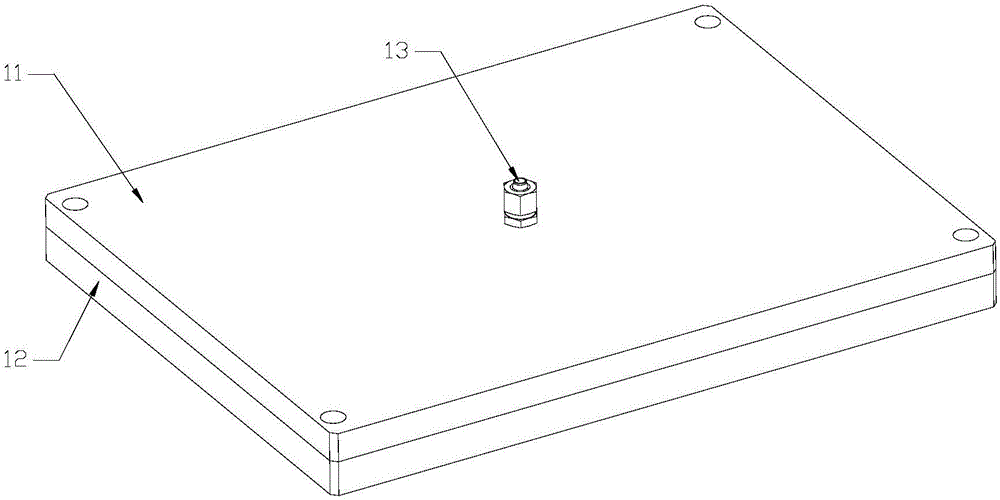
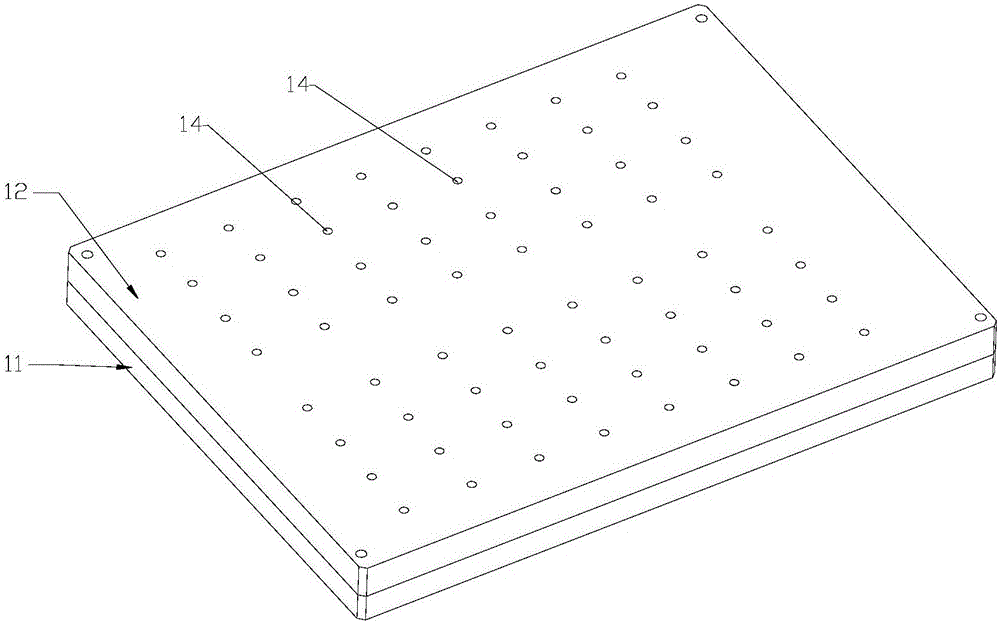
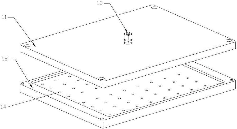
The invention discloses a gas sensor testing device and a testing method. The testing device comprises a gas distributing device, a gas supply device and a signal collection device, wherein the gas distributing device is used for distributing and providing gas for testing; the gas supply device is used for distributing tested gas and comprises a gas inlet plate and a gas outlet plate; the gas inlet plate and the gas outlet plate are connected into a whole body in a sealed way, so that a cavity is formed in the interior between the gas inlet plate and the gas outlet plate; the gas inlet plate is provided with a gas inlet used for being communicated with the cavity and the air distributing device; the gas outlet plate is provided with a plurality of gas outlets used for being communicated the cavity and an inlet of a gas sensor; the signal collection device is used for collecting inductive signals of the gas sensor. The testing device can realize rapid testing and batch detecting of the gas sensor, and saves the gas for testing.

Description

technical field [0001] The invention relates to the technical field of gas sensor testing, and more particularly, to a gas sensor testing device and a gas sensor testing method. Background technique [0002] Gas sensors are used to detect the type of gas or measure the concentration of gas. The test accuracy of the gas sensor is a crucial indicator. Factory testing of gas sensors is a critical process. [0003] At present, the gas sensor test is generally completed in the gas sensor test box (or test box). During the test, the gas sensor needs to be placed in the test box, the entire test box is filled with the target gas, and the gas sensor is placed in the target gas atmosphere to complete the test. The entire process is almost entirely done manually. There are the following problems in this test method: one is waste of gas, the amount of the target gas detected by the gas sensor is very small, and there is no need for a full box of target gas, but the test needs to fi...

Claims


Application Information

Patent Timeline
Patent Type & Authority Applications(China)
IPC IPC(8): G01N33/00
CPCG01N33/007G01N33/0072
Inventor 王德信巩向辉鱼婧
Owner WEIFANG GOERTEK MICROELECTRONICS CO LTD
Learn More