
A shock wave free-field pressure measurement structure for shock tube calibration

A shock tube and shock wave technology, which is applied in the installation structure field of shock wave free field pressure test, can solve the problems that the dynamic characteristics of the shock wave free field pressure test system cannot be obtained, and how many changes cannot be considered, so as to achieve a firm and reliable structure and high safety Effect

Active Publication Date: 2019-03-08
XIAN MODERN CHEM RES INST
View PDF7 Cites 0 Cited by
  • Summary
  • Abstract
  • Description
  • Claims
  • Application Information

AI Technical Summary

Problems solved by technology

Such a calibration method does not consider the impact of the installation structure on the entire pressure measurement system during the actual shock wave free-field pressure measurement. It can only calibrate the dynamic sensitivity of the pressure sensor and obtain the dynamic characteristics of the pressure sensor, and cannot consider the calibration of the excitation waveform when the actual pen-shaped structure is used. How much does its waveform change when it reaches the pressure sensor, and it is impossible to obtain the dynamic characteristics of the actual shock wave free-field pressure test system

Method used


Image

  • A shock wave free-field pressure measurement structure for shock tube calibration
  • A shock wave free-field pressure measurement structure for shock tube calibration
  • A shock wave free-field pressure measurement structure for shock tube calibration

Examples


Embodiment 1

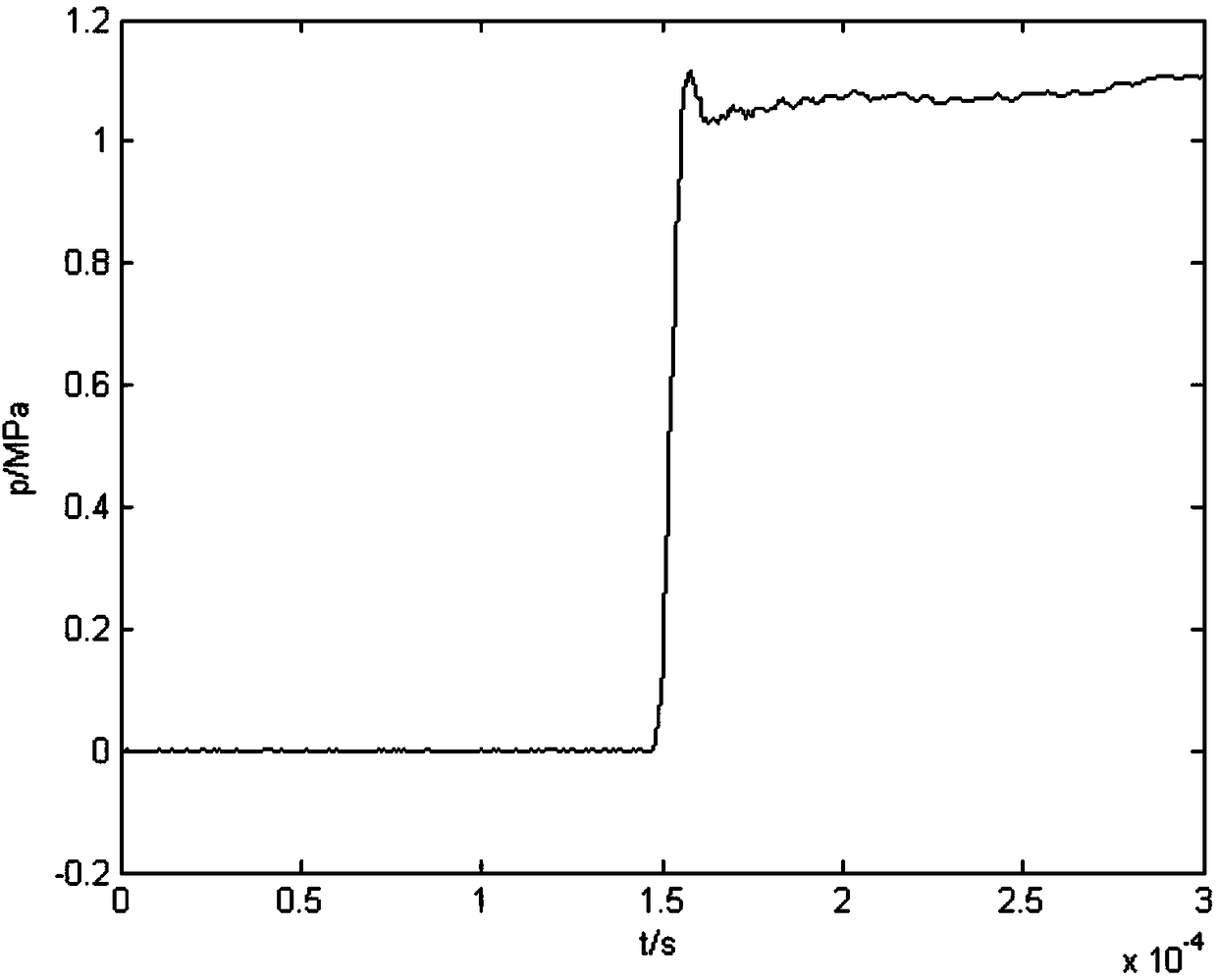
[0033] Use the PCB 113 pressure sensor as the sensor to be calibrated, install it on the pen-shaped structure, and then install the pen-shaped structure on the mounting base. Put the sealing ring in the empty groove of the mounting seat, and place it at the end of the GXJ-100s high-voltage shock tube developed by 204. Use the same type of pressure sensor to install on the side wall of the end of the shock tube, and then start the hydraulic cylinder to seal the low-pressure section of the shock tube. After installing the diaphragm in the sandwiched section of the shock tube, seal the sandwiched section and the high-pressure section. First inflate the low-pressure section, then inflate the sandwich section, then inflate the high-pressure section, and finally deflate the sandwich section, the diaphragm ruptures, and an ideal step wave acts on the mounting seat.

[0034] The pressure signal output by the free-field manometry system is as follows: image 3As shown, the incident p...


PUM

PropertyMeasurementUnit
diameteraaaaaaaaaa
thicknessaaaaaaaaaa
diameteraaaaaaaaaa

Abstract

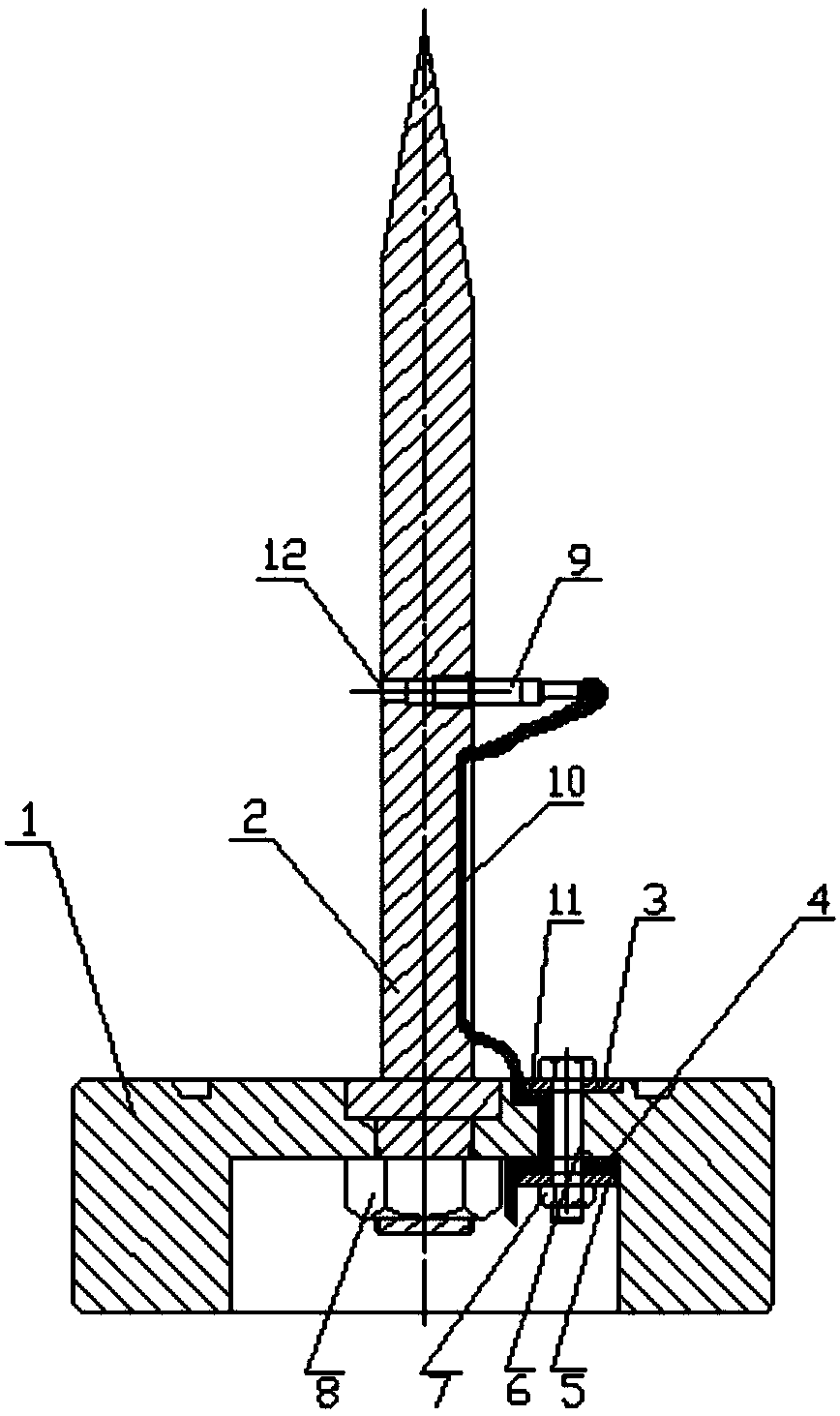
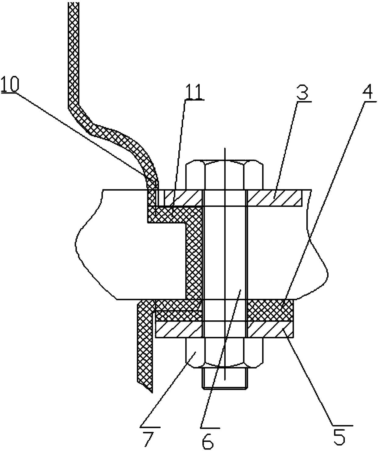
The invention discloses a shock-wave free-field pressure measuring structure for the calibration of a shock tube, and belongs to the technical field of dynamic calibration. The structure is used for measuring shock wave free field pressure under the damage condition, and can be installed at the tail end of the shock tube for dynamic calibration. The structure comprises an installation seat, a pen-shaped structure, an upper wire-pressing plate, a cushion pad, a lower wire-pressing plate, a screw, a small nut, a big nut, a pressure sensor, a signal line, sealing glue, and thermal isolation grease. The structure is firm and reliable, is high in safety, and achieves the full sealing during the stringing of the signal line. During testing, the gas in the shock tube is not leaked; after testing, the signal line does not slide and does not need to be drawn back. The structure can achieve the dynamic calibration of a shock-wave free-field pressure measurement system under the actual damage condition, and obtain the dynamic characteristics of the actual shock-wave free-field pressure measurement system.

Description

technical field [0001] The invention belongs to the technical field of sensor calibration, and in particular relates to an installation structure for a shock wave free field pressure test. The structure is installed at the end of a shock wave tube for dynamic calibration to obtain the dynamic characteristics of a corresponding shock wave free field pressure test system. Background technique [0002] Shock wave pressure is an important basis for consideration in the assessment of blast field power. When measuring the shock wave free-field pressure in the actual shooting range, a pen-shaped structure is often used, the tip of the pen points to the explosion center, the pressure sensor is installed in the center, and the end face is flush with the end face of the pen-shaped structure after being coated with heat-insulating grease, forming a shock wave free-field pressure test structure. [0003] In the past research work, when performing dynamic calibration on the shock wave fr...

Claims


Application Information

Patent Timeline
Patent Type & Authority Patents(China)
IPC IPC(8): G01L25/00
CPCG01L25/00
Inventor 孔霖苏健军胡东常李尚青魏巍姬建荣张俊锋何性顺
Owner XIAN MODERN CHEM RES INST
Learn More