
Frost resistance water meter

A water meter and movement technology, which is applied in measuring devices, instruments, liquid/fluid solid measurement, etc., can solve problems such as low glass strength, and achieve the effect of avoiding freezing damage.

Pending Publication Date: 2017-05-10
何竺灵 +1
View PDF7 Cites 6 Cited by
  • Summary
  • Abstract
  • Description
  • Claims
  • Application Information

AI Technical Summary

Problems solved by technology

After research and analysis, 98% of the cracks in the water meter are due to damage to the watch glass, because after the water freezes, the water in the water meter casing changes from liquid to solid ice, which increases in volume and expands outward, and the strength of glass is lower than that of metal. Easily damaged by water leaks first

Method used


Image

  • Frost resistance water meter
  • Frost resistance water meter
  • Frost resistance water meter

Examples


Embodiment 1

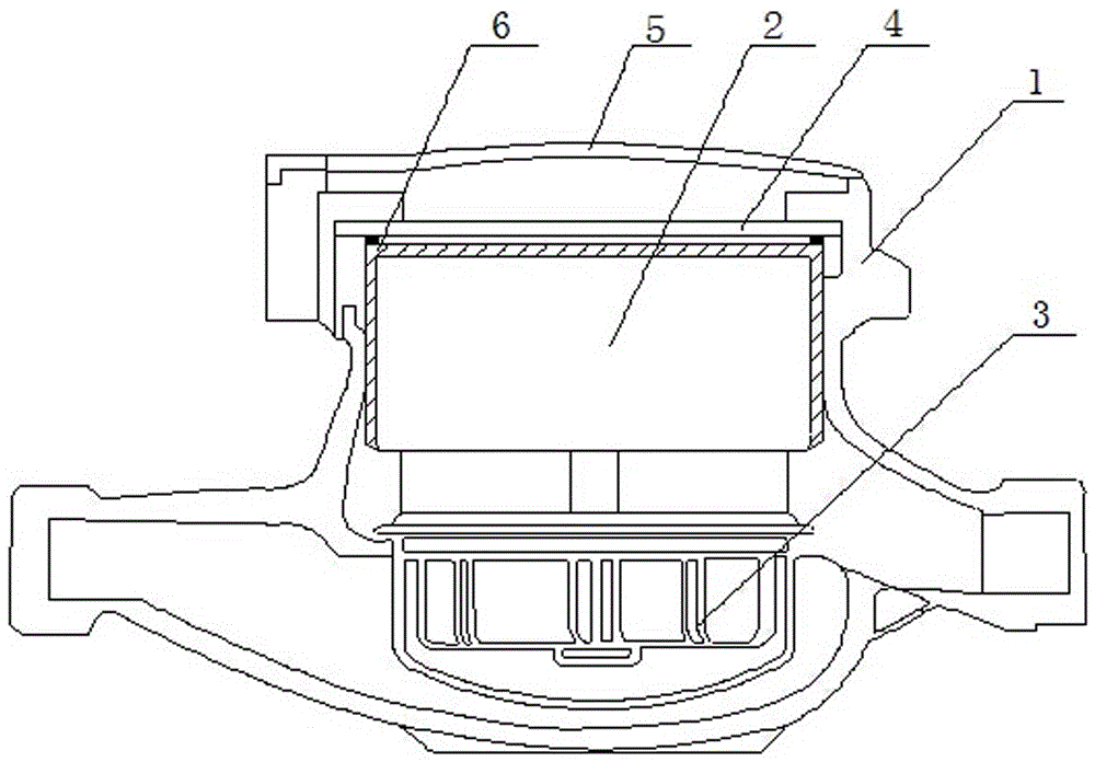
[0016] Such as figure 1 As shown, in the case of the existing water meter structure, (the existing water meter includes a housing 1, a core 2 placed in the housing 1, an impeller assembly 3 connected to the core 2, and a Table glass plate 4 and flip cover 5), an airtight inverted U-shaped transparent cover 6 made of hard transparent plastic is buckled outside the movement, so that the air in the top of the water meter and the movement cannot be discharged from the top of the movement. Water enters from the water inlet of the water meter and flows quickly to the water outlet. At this time, since the air in the lower part of the water meter and the movement cannot be discharged from the upper part of the movement, a water-sealed air is formed in the transparent cover (ie, the upper part of the movement). Cavity, that is, the gas-liquid balance is realized in the water meter, so that water cannot enter the upper part of the movement (generally, the water level is below the dial)....

Embodiment 2

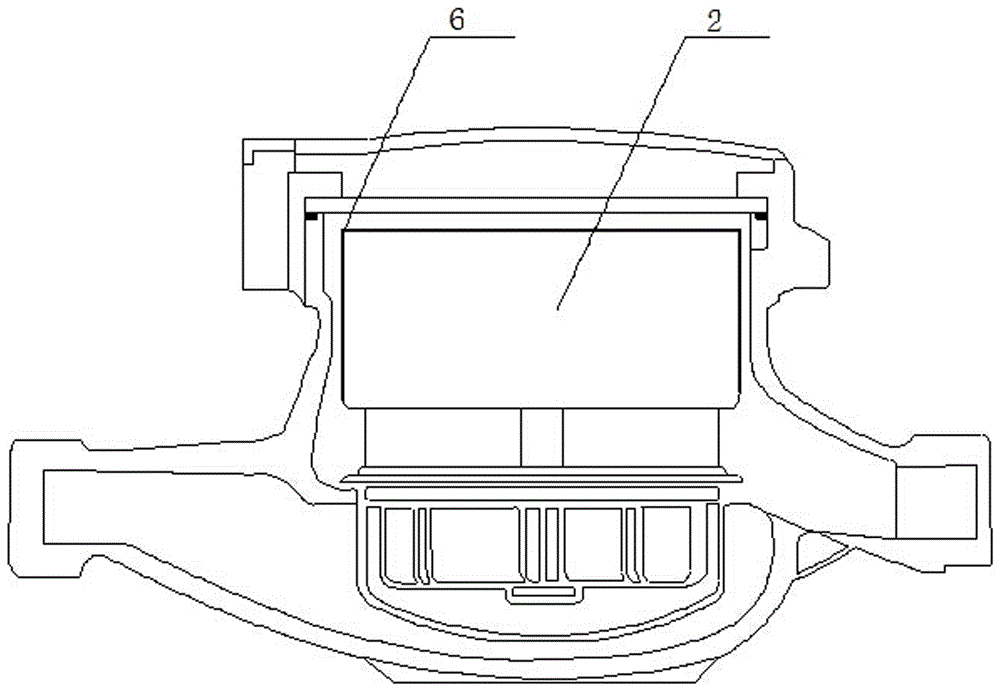
[0018] Such as figure 2 As shown, the inverted U-shaped transparent cover 6 is made of heat-shrinkable film, and the inverted U-shaped transparent cover is closely attached to the outside of the movement 2 .

[0019] Other structures are with embodiment 1.

Embodiment 3

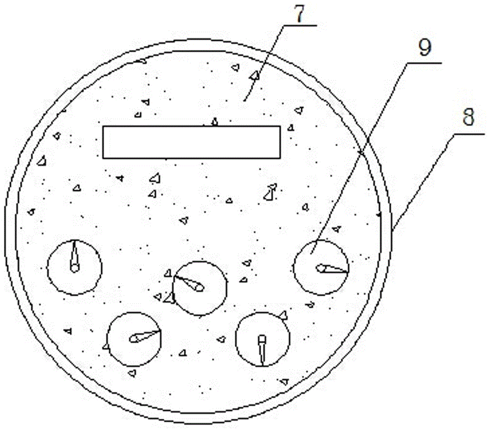
[0021] Such as image 3 As shown, the top of the movement is a dial 8, and the gap between the pointer 9 and the pointer 9 is filled with a high foaming polymer 7 inside the dial 8 to ensure the proportion of air inside the movement. When the inverted U-shaped transparent cover fails, the high-foaming polymer 7 can absorb the expansion force when water becomes solid, so as to prevent the watch glass from being damaged by freezing.

[0022] It should be noted here that the top of the movement and the bottom of the dial can also be filled with gas-containing polymers or aerosols to increase the gas content inside the movement.


PUM


Abstract

The invention discloses a frost resistance water meter. The water meter comprises a shell body, a movement arranged in the shell body, an impeller assembly connected with the movement, and a meter glass plate and a flipping cover arranged at the top of the shell body. An inverted U-shaped transparent cover that is capable of preventing air inside the movement from discharging through the upper part of the movement is arranged outside the movement in a sealed mode. The frost resistance water meter has the advantages that a sealed transparent cover is additionally arranged outside the water meter movement, and therefore the air at the upper part of the water meter and in the movement can not be discharged from the upper part of the movement, water content in the water meter not exceed 95% is guaranteed, which is to say, an air cavity sealed by water is arranged in the transparent cover(upper part of the movement), a gas-liquid equilibrium state is reached in the water meter, and therefore water cannot enter the upper part of the movement(normally the water level is below a dial). When temperature reaches freezing point, because of the cavity arranged at the upper part of the water meter movement, ice expanses into the cavity when frozen, the ice cannot directly squeeze the meter glass and the shell body, frost damage of the meter glass and the shell body is avoided, and the function of frost resistance is achieved.

Description

technical field [0001] The invention relates to an antifreeze water meter, which belongs to the field of instruments and instruments for preventing damage caused by volume changes caused by solid-liquid transformation. Background technique [0002] Most of the existing antifreeze and antifreeze water meters adopt methods such as energy absorption, pressure relief, temperature-controlled pressure relief, and temperature-controlled electric heating to achieve antifreeze and antifreeze. For example, patents CN201145599Y, CN202676223U, CN106123990A, etc. After research and analysis, 98% of the cracks in the water meter are due to damage to the watch glass, because after the water freezes, the water in the water meter casing changes from liquid to solid ice, which increases in volume and expands outward, and the strength of glass is lower than that of metal. It is easy to damage and leak first. For this reason, how to reduce the water content in the water meter is the most effe...

Claims


Application Information

Patent Timeline
IPC IPC(8): G01F15/10G01F15/14
CPCG01F15/10G01F15/14
Inventor 何竺灵何曜华
Owner 何竺灵
Learn More