Drying tower

A technology of drying tower and tower body is applied in drying, drying machine, drying solid materials and other directions, which can solve the problems of poor drying effect and low drying efficiency of upper materials, improve drying efficiency and facilitate maintenance. , the effect of reducing drying costs

Active Publication Date: 2017-05-10
四川南江新兴矿业有限公司
View PDF5 Cites 0 Cited by
  • Summary
  • Abstract
  • Description
  • Claims
  • Application Information

AI Technical Summary

Problems solved by technology

[0002] Existing drying towers usually only have one heat source inlet located at the lower part of the tower body. After the hot air enters the tower body, it first takes away the moisture of the materials below, and the humid hot air continues upward. The drying effect on the materials above is obviously poor. low efficiency

Method used


Image

  • Drying tower
  • Drying tower

Examples


Embodiment Construction

[0013] In order to make the purpose, technical solution and advantages of the present application clearer, the present application will be further described in detail below in conjunction with the accompanying drawings and specific embodiments. For simplicity, some technical features known to those skilled in the art are omitted from the following description.

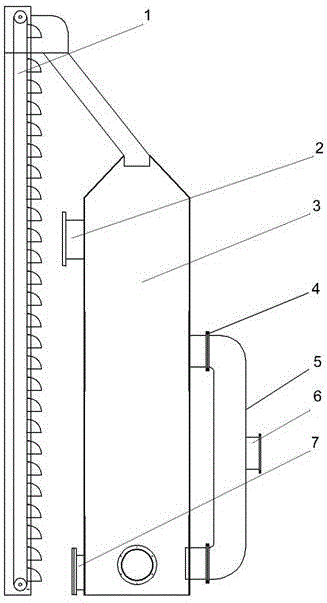
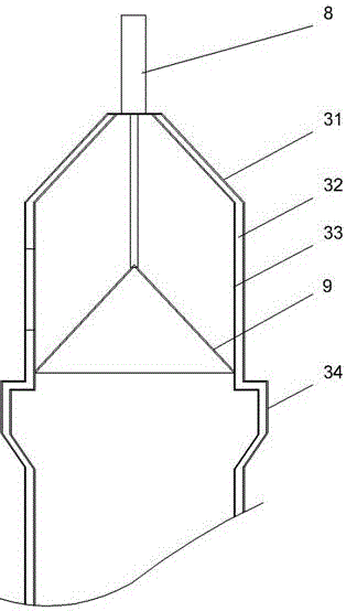
[0014] The invention provides a drying tower, such as figure 1 As shown, it includes a tower body 3 and a U-shaped hot air pipe 5. The top of the tower body 3 is provided with a feed inlet, and the position near the bottom of the tower body 3 is provided with a discharge port. The middle part of the tower body 3 is provided with an upper hot air outlet. There is a lower hot air outlet; one end of the hot air pipe 5 is connected to the upper hot air outlet, and the other end is connected to the lower hot air outlet, and both ends of the hot air pipe 5 are provided with solenoid valves 4, and the middle part of the hot a...


PUM


Abstract

The invention provides a drying tower. The drying tower comprises a tower body, wherein a charge port is formed in the top of the tower body, a discharge port is formed in a position close to the bottom, of the tower body, an upper hot-air port is formed in the middle part of the tower body, and a lower hot-air port is formed in the lower part of the tower body. The drying tower further comprises a U-shaped hot-air pipe, wherein one end of the hot-air pipe is connected with the upper hot-air port, the other end of the hot-air pipe is connected with the lower hot-air port, electromagnetic valves are arranged at the two ends of the hot-air pipe, and a main hot-air port is formed in the middle part f the hot-air pipe. The hot-air ports are formed in the middle part and the lower part of the tower body respectively, dry hot air can be generated twice during a material falling process, thus the drying efficiency is increased and the drying cost is lowered. A conical meshy material tray is arranged in the tower body above a widening part, a cylinder piston pushes the material tray to move downwards during use, the bottom surface of the material tray is enabled to be located in the widening part, the hot air arrives at the space above the material tray through meshes to pre-dry materials above, and then the materials slide off from a gap between the tray and the widening part to be formally dried, thus the drying efficiency is further increased.

Description

technical field [0001] The invention belongs to the field of drying equipment, and in particular relates to a drying tower. Background technique [0002] Existing drying towers usually only have one heat source inlet located at the lower part of the tower body. After the hot air enters the tower body, it first takes away the moisture of the materials below, and the humid hot air continues upward. The drying effect on the materials above is obviously poor. low efficiency. Contents of the invention [0003] The object of the present invention is to provide a drying tower, which can well solve the above problems. [0004] In order to meet the above requirements, the technical solution adopted by the present invention is to provide a drying tower, including a tower body, a feed inlet is arranged on the top of the tower body, a discharge outlet is arranged near the bottom of the tower body, and a drying outlet is arranged in the middle of the tower body There is an upper hot ...

Claims


Application Information

Patent Timeline
Patent Type & Authority Applications(China)
IPC IPC(8): F26B9/06F26B21/02F26B25/18F26B25/02
CPCF26B9/06F26B21/02F26B25/02F26B25/18
Inventor 颜洪王清朗王家定
Owner 四川南江新兴矿业有限公司
Why Eureka
Try Eureka