
A diversion shell type two-stage double-suction centrifugal pump

A technology of a guide shell and a centrifugal pump, which is applied to the components of a pumping device for elastic fluid, a non-variable-capacity pump, a radial flow pump, etc. Due to the small axial size of the radial guide vanes and the huge size of the bridge, the effects of strong cavitation resistance, wide flow channel and small lift are achieved.

Active Publication Date: 2019-01-22
CHINA AGRI UNIV
View PDF7 Cites 1 Cited by
  • Summary
  • Abstract
  • Description
  • Claims
  • Application Information

AI Technical Summary

Problems solved by technology

However, for the transition channel type two-stage double-suction centrifugal pump, due to the large size of the bridge, the sharp turn of the channel, and the complex structure, it is difficult to pump liquids containing large particles or flexible long-fiber media.
For the radial guide vane type two-stage double-suction centrifugal pump, the axial size of the radial guide vane is small, the throat area is small, and the fluid is quickly adjusted between the positive guide vane and the reverse guide vane. When the liquid of long fiber medium is used, it is easy to cause flow channel blockage
[0003] In addition, the heads of the two-stage impellers of the transition channel type and the radial guide vane type two-stage double-suction centrifugal pump are equal, that is, they are both half of the total head of the pump, which leads to the same specific speed of the two-stage impellers, although this is in To some extent, the hydraulic design is simplified so that the blades of the two-stage impellers are made using the same wooden pattern, but the cavitation performance and suction capacity of the first-stage impeller are poor.

Method used


Image

  • A diversion shell type two-stage double-suction centrifugal pump
  • A diversion shell type two-stage double-suction centrifugal pump
  • A diversion shell type two-stage double-suction centrifugal pump

Examples


Embodiment Construction

[0030] The present invention will be described in detail below in conjunction with the accompanying drawings and embodiments.

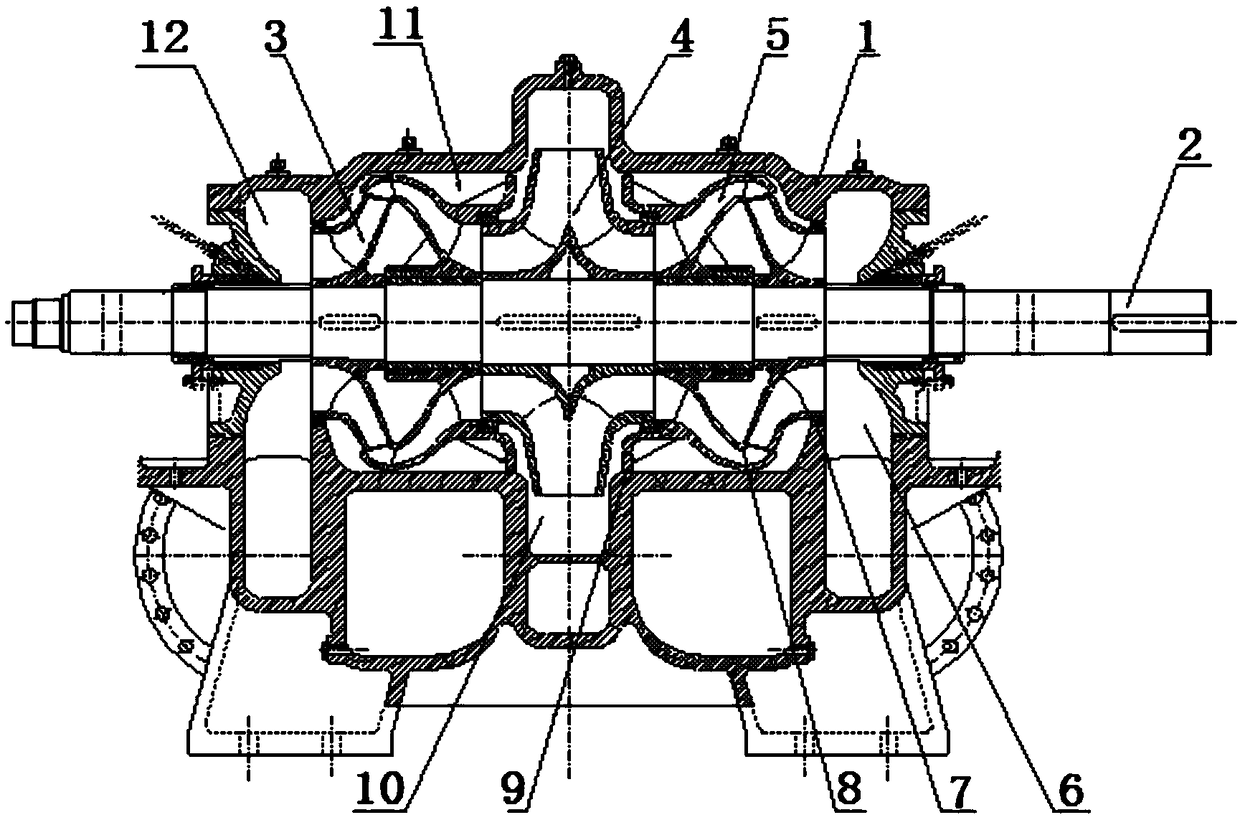
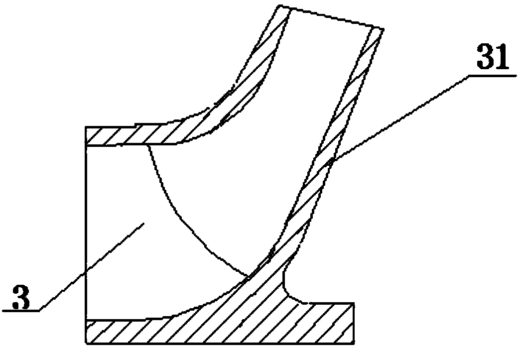
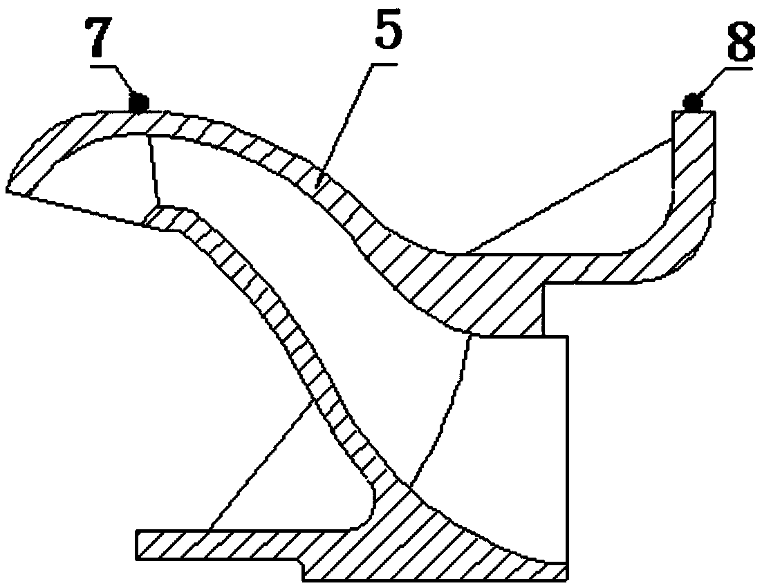
[0031] like Figure 1~3 As shown, the present invention proposes a diversion casing type double-stage double-suction centrifugal pump, which includes a pump body 1 and a transmission shaft 2 that runs through the pump body 1 and is rotatably connected with the pump body 1. Two first-stage impellers 3 are arranged at intervals on the transmission shaft 2, a second-stage impeller 4 is arranged on the transmission shaft 2 between the two first-stage impellers 3, and an interstage guide casing is fixedly arranged in the pump body 1. 5. The interstage diversion shell 5 is an impeller, its flow channel is S-shaped, the flow channel is wide and the turning is smooth, it is located between the first stage impeller 3 and the second stage impeller 4, the inlet end of the interstage diversion shell 5 and The outlet end of the first-stage impeller 3 is connected...


PUM


Abstract

The invention relates to a flow diversion shell type double-stage double-suction centrifugal pump. The flow diversion shell type double-stage double-suction centrifugal pump comprises a pump body and a transmission shaft penetrating through the pump body and rotationally connected with the pump body. Two first-stage impellers are arranged on the part, located in the pump body, of the transmission shaft front and back in a spaced mode. A second-stage impeller is arranged on the part, located between the two first-stage impellers, of the transmission shaft. An interstage flow diversion shell is fixedly arranged in the pump body and is an impeller. A runner of the interstage flow diversion shell is in an S shape. The interstage flow diversion shell is located among the first-stage impellers and the second-stage impeller. The inlet end of the interstage flow diversion shell is connected with the outlet ends of the first-stage impellers. The outlet end of the interstage flow diversion shell is connected with the inlet end of the second-stage impeller.

Description

technical field [0001] The invention relates to a double-stage centrifugal pump, in particular to a diversion shell type double-stage double-suction centrifugal pump. Background technique [0002] The double-inlet two-stage double-suction centrifugal pump has the characteristics of large flow rate and high head, and has broad application prospects in high-lift water lifting projects. At present, there are mainly two types of double-inlet two-stage double-suction pumps: transition channel type and radial guide vane type. The transition channel type two-stage double-suction centrifugal pump adopts the method of double-inlet volute and bridge to introduce the liquid from the first-stage impeller to the second-stage impeller, while the radial guide vane type two-stage double-suction centrifugal pump directs the water flow from the radial guide vane to the second-stage impeller. The first stage impeller leads to the second stage impeller. However, for the transition channel typ...

Claims


Application Information

Patent Timeline
Patent Type & Authority Patents(China)
IPC IPC(8): F04D1/06F04D29/22F04D29/44F04D29/16F04D29/66
CPCF04D1/06F04D29/167F04D29/2216F04D29/448F04D29/669
Inventor 王福军叶长亮肖若富姚志峰杨魏陈鑫
Owner CHINA AGRI UNIV
Learn More