
An assembled energy-dissipating beam-column joint

A beam-column joint and assembly technology, applied in protected buildings/shelters, building types, buildings, etc., can solve problems such as structural damage, inoperability, and huge maintenance costs

Active Publication Date: 2019-06-21
HUNAN UNIV
View PDF8 Cites 0 Cited by
  • Summary
  • Abstract
  • Description
  • Claims
  • Application Information

AI Technical Summary

Problems solved by technology

However, for the plastic design idea of ​​structural yielding, dissipating the energy input into the building structure by earthquakes and wind disasters also means damage to the structure itself, which creates a problem: to restore the structure to the level of resistance before the damage occurs, it must be corrected. Replacement or reinforcement of damaged components may result in huge maintenance costs, and in some cases it will become inoperable; in addition, if the maintenance work on the building structure affects the use of the building, it will bring a greater psychological impact on the public. impact, leading to public doubts about the safety of the building

Method used


Image

  • An assembled energy-dissipating beam-column joint
  • An assembled energy-dissipating beam-column joint
  • An assembled energy-dissipating beam-column joint

Examples


Embodiment Construction

[0020] The present invention will be further described below in conjunction with the accompanying drawings and embodiments.

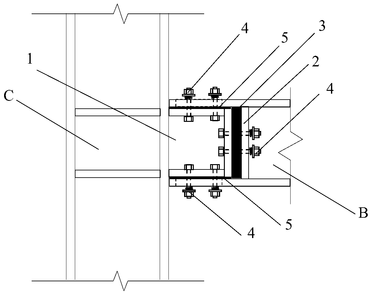
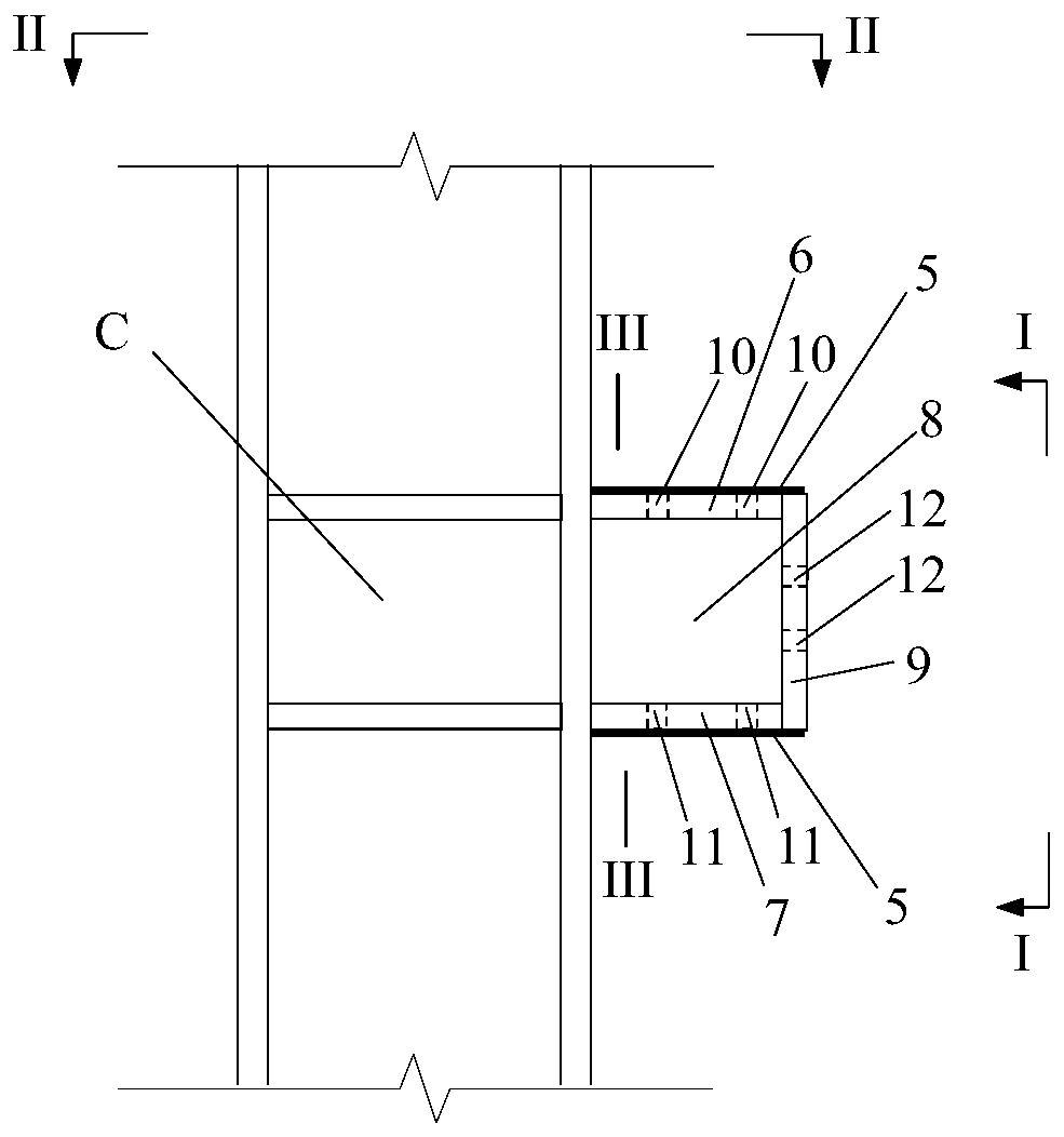
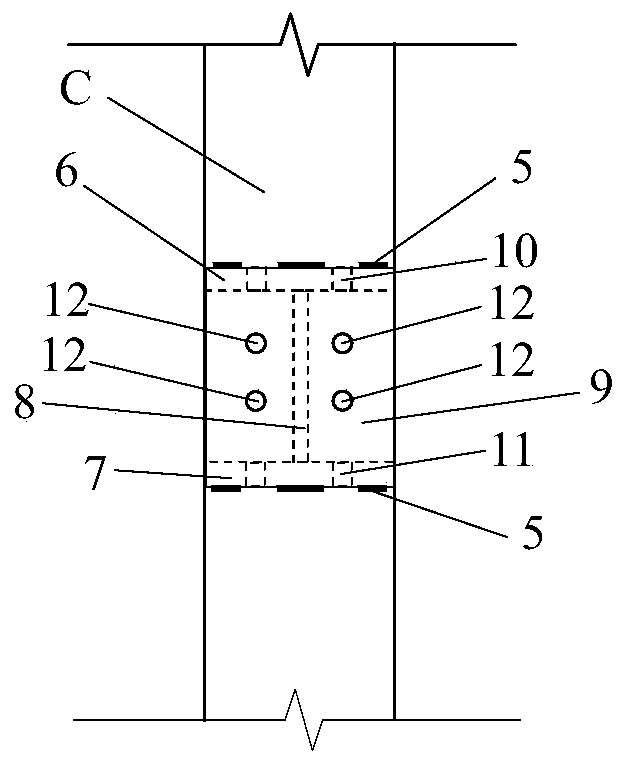
[0021] refer to Figure 1-8 , this embodiment includes a cantilever convex section 1 welded on the column C, a beam end notch 2, a rubber pad 3, and a bolt connection pair 4. The cantilever convex section 1, beam end notch 2, and rubber pad 3 are connected by bolts 4 connected as a whole; the cantilever convex section welded on the column C is composed of the upper flange 6, the lower flange 7, the web 8, the end plate 9 and the friction between the upper surface of the upper flange and the lower surface of the lower flange. The element 5 (made of viscoelastic material), the upper flange 6, the lower flange 7, and the web 8 are welded to form an I-shaped section, and the end plate 9 is connected to the upper flange 6, the lower flange 7, The web 8 is welded and connected, the upper flange 6 has a circular bolt hole 10, the lower flange 7 has a circular...


PUM


Abstract

The invention discloses an assembly type energy consumption beam column node, comprising a cantilever convex section, a beam end concave opening, a rubber cushion block, and a bolt connecting pair which are welded to the column; the cantilever convex section, the beam end concave opening, and the rubber cushion block are connected to be one body through the bolt connecting pair; the cantilever convex section consists of an upper wing edge, a lower wing edge, a web plate, an end plate, and a friction element bonded to the upper surface of the upper wing edge and the lower surface of the lower wing edge; the upper wing edge, the lower wing edge, and the web plate are formed to be a transverse-H shaped section; circular bolt holes are arranged on the upper wing edge, the lower wing edge and the end plate; the beam end concave opening consists of an upper overhanging wing edge, a lower overhanging wing edge, and a bottom plate of the transverse-H shaped section beam; waist bolt holes are formed on the upper overhanging wing edge and the lower overhanging wing edge, and the circular bolt hole is formed on the bottom plate. The assembly type energy consumption beam column node can automatically reset and slip in earthquake or fire disaster, so ass to realize the reciprocating friction and energy consumption, guarantee that node has stable and high-efficient energy consumption ability in the whole disaster process, avoid brittle failure of the rigid node, and thereby reducing the repair cost after disaster.

Description

technical field [0001] The invention relates to an energy-dissipating beam-column joint in the construction field, in particular to an assembled energy-dissipating beam-column joint. Background technique [0002] The beam-column joints of the frame structure are rigid, have a large bearing capacity and lateral stiffness, and are a typical multi-story structure system. The rigid joints reduce the energy dissipation capacity of the structure under dynamic loads such as earthquakes and winds, and brittle failures are prone to occur during strong earthquakes or strong winds. In order to safely and effectively resist strong earthquakes and strong winds, and reduce the peak loads of earthquakes and wind disasters on building structures, there is also a plastic design idea of ​​turning to make the structure yield. However, for the plastic design idea of ​​structural yielding, dissipating the energy input into the building structure by earthquakes and wind disasters also means dama...

Claims


Application Information

Patent Timeline
Patent Type & Authority Patents(China)
IPC IPC(8): E04B1/58E04B1/98E04B1/24E04H9/02
CPCE04B1/2403E04B1/5812E04B2001/2418E04B2001/2448E04B2001/5856E04H9/02E04H9/024
Inventor 贺拥军周绪红王继新
Owner HUNAN UNIV
Learn More