
UHPC-common-concrete-lamination composite bridge-deck-slab construction and constructing method thereof

A common concrete and concrete technology, applied in bridges, bridge parts, bridge construction, etc., can solve problems such as stress concentration, large block size, unreliable connection between steel bridge deck and asphalt concrete, etc., to eliminate local stress concentration, shear force transmission continuous effect

Active Publication Date: 2017-05-10
SOUTHEAST UNIV
View PDF6 Cites 20 Cited by
  • Summary
  • Abstract
  • Description
  • Claims
  • Application Information

AI Technical Summary

Problems solved by technology

[0003] The steel bridge deck has the problem of welding fatigue damage, and the connection between the steel bridge deck and the asphalt concrete is unreliable; the cast-in-place ordinary concrete bridge deck needs to be set with transverse prestress, and the construction process requires brackets, which is inconvenient for construction; the precast concrete bridge deck has a large block size. It is not easy to hoist, and the prefabricated slab and the steel beam are connected by cluster nails, the shear force transmission is discontinuous, and there is a phenomenon of stress concentration

Method used


Image

  • UHPC-common-concrete-lamination composite bridge-deck-slab construction and constructing method thereof
  • UHPC-common-concrete-lamination composite bridge-deck-slab construction and constructing method thereof
  • UHPC-common-concrete-lamination composite bridge-deck-slab construction and constructing method thereof

Examples


Embodiment Construction

[0026] The present invention will be further described below in conjunction with the accompanying drawings and specific embodiments.

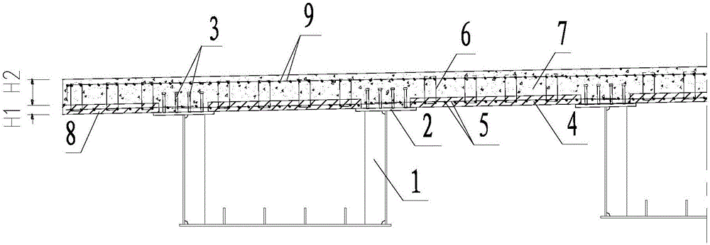
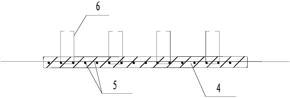
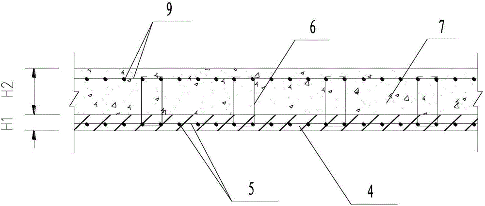
[0027] Such as Figure 1-6 As shown, a UHPC-ordinary concrete laminated composite bridge deck structure, including UHPC prefabricated slab 4, horizontal pre-embedded reinforcement 5, U-shaped vertical pre-embedded reinforcement 6, laminated cast-in-place concrete 7, vertical and horizontal overall reinforcement mesh 9. Concrete 10 and shear nail 3 with wet joint;

[0028] The shear stud 3 is welded on the surface of the flange plate 2 of the steel beam 1, and the UHPC prefabricated panel 4 is provided with a horizontal pre-embedded steel bar 5 and a U-shaped vertical pre-embedded bar 6, and the U-shaped vertical pre-embedded bar 6 Expose the top surface of the UHPC prefabricated panel 4, and expose the joint surface of the UHPC precast panel 4 horizontally to the pre-embedded steel bar 5. The UHPC precast panel 4 is supported on the flange pla...


PUM

PropertyMeasurementUnit
Thicknessaaaaaaaaaa
Thicknessaaaaaaaaaa

Abstract

The invention discloses a UHPC-common-concrete-lamination composite bridge-deck-slab construction and a constructing method thereof. The UHPC-common-concrete-lamination composite bridge-deck-slab construction comprises UHPC prefabricated slabs, horizontal pre-embedded reinforcing steel bars, U-shaped vertical pre-embedded bars, lamination cast-in-place concrete, vertical-and-horizontal whole reinforcing steel bar nets, wet-connection-band concrete and steel-beam-flange-slab shearing nails. The steel-beam-flange-slab shearing nail are welded on the surfaces of flange slabs of steel beams, the UHPC prefabricated slabs are supported on the flange slabs of the steel beams, and the horizontal pre-embedded reinforcing steel bars between the adjacent UHPC prefabricated slabs are in lap joint; the vertical-and-horizontal whole reinforcing steel bar nets are arranged on the flange slabs of the steel beams and the UHPC prefabricated slabs and poured with the lamination cast-in-place concrete, and the UHPC prefabricated slabs are poured with the wet-connection-band concrete. A UHPC-common-concrete-lamination composite bridge deck slab has the advantages that the structural stress performance is excellent, the weight of the bridge deck slab is light, the performance cost ratio is high, shear transferring is continuous, transverse prestress is not required, and support-free constructing can be achieved, cooperative work of the steel beams and the concrete bridge deck slab can be achieved, and carrying capacities of composite beams are improved.

Description

technical field [0001] The invention belongs to the technical field of bridge engineering, and relates to a composite bridge deck structure of a steel-concrete composite bridge, in particular to a UHPC-ordinary concrete laminated composite bridge deck structure and a construction method thereof. Background technique [0002] At present, my country is vigorously promoting composite structure bridges and steel structure bridges. In July 2016, the Ministry of Transport issued the "Guiding Opinions on Promoting the Construction of Highway Steel Structure Bridges", which decided to promote the construction of steel bridges and steel-concrete composite beam bridges, improve the quality of my country's highway bridges, and promote the transformation and upgrading of highway construction. The steel-concrete composite girder bridge can give full play to the characteristics of steel and concrete, and is a kind of steel-concrete bridge structure with excellent performance. [0003] Th...

Claims


Application Information

Patent Timeline
IPC IPC(8): E01D19/12E01D21/00
CPCE01D19/125E01D21/00
Inventor 刘钊卓为顶张文明
Owner SOUTHEAST UNIV
Learn More