drop test tower
What is Al technical title?
Al technical title is built by PatSnap Al team. It summarizes the technical point description of the patent document.
A technology of oil cylinders and stands, applied in the field of falling test towers, which can solve problems such as detachment, slack of suspension wire ropes, rebound of decoupling devices, etc., and achieve the effect of high operating efficiency
Active Publication Date: 2019-11-15
SHANGHAI JIAOTONG UNIV
View PDF8 Cites 0 Cited by
Summary
Abstract
Description
Claims
Application Information
AI Technical Summary
This helps you quickly interpret patents by identifying the three key elements:
Problems solved by technology
Method used
Benefits of technology
Problems solved by technology
During use, the decoupling device adopts the working mode of remote triggering and manual approach reset; the tested device is moved under the heavy object by manpower, which is less safe; if the test mass is large, when the external weight is released, it is stored in the hanging wire rope The energy of the decoupling device will cause the rebound of the decoupling device, causing the suspension wire rope to slack, de-groove and other faults
Method used
Image
Click on the blue label to locate the original text in one second.
Reading with bidirectional positioning of images and text.
Examples
Embodiment Construction
[0036] The present invention will be described in detail below in conjunction with specific embodiments. The following examples will help those skilled in the art to further understand the present invention, but do not limit the present invention in any form. It should be noted that those skilled in the art can make several changes and improvements without departing from the concept of the present invention. These all belong to the protection scope of the present invention.
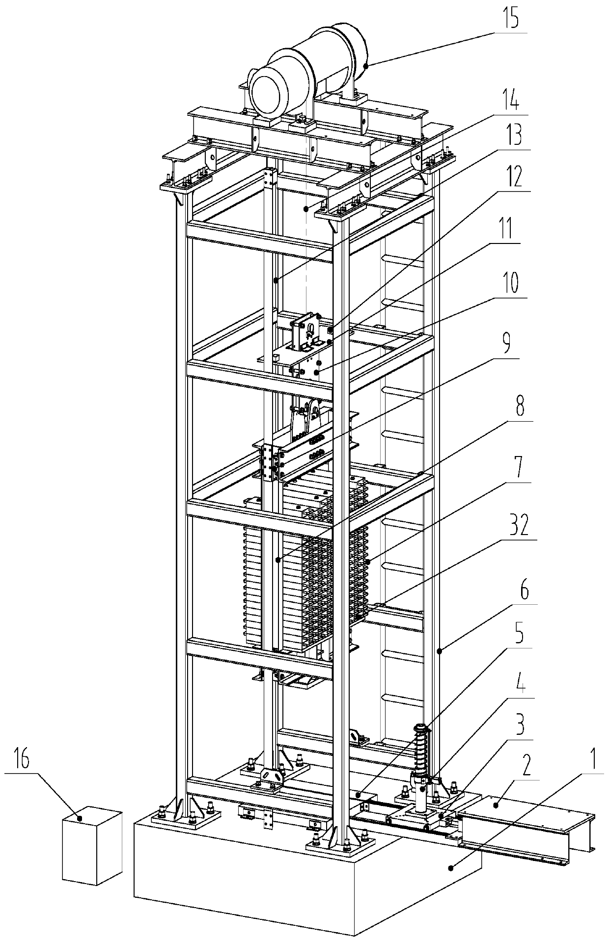
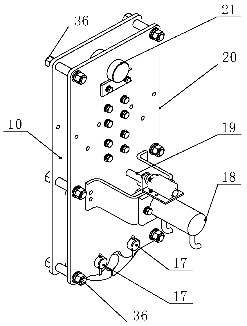
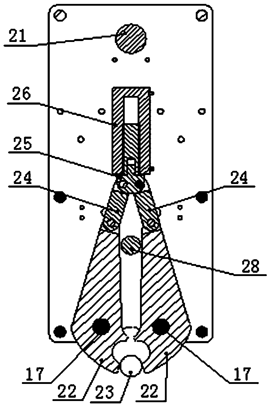
[0037] Such as Figure 1 to Figure 5 As shown, a drop test tower provided by the present invention includes a base 1, a stand 6 is arranged on the base 1, a guide rail 13 is provided in the stand 6, a lifting device 15 is provided on the top of the stand 6, and a lifting device 15 is provided on the guide rail 13. The inside is provided with a car 32 that can move along the guide rail 13, and a certain number of weights 7 are arranged in the car 32, and the quantity of the weights 7 can be increased or ...
PUM
Abstract
The invention provides a falling testing tower which comprises a base, a push oil cylinder, a push vehicle body, a buffering plate, a tower frame, heavy blocks, a testing frame, a guide shoe, an unhooking mechanism, an unhooking mechanism guiding device, guide rails, a lifting steel wire rope, a lifting device and a pump station. The falling testing tower is suitable for falling testing of safety tongs and buffers which have different strokes and different testing quality. The falling testing tower is characterized in that firstly, the unhooking mechanism can remotely released or reset or being connected with or disengaged from a lift car, people do not need to get close to the tower for operation, and due to the fact that a safety pin is adopted, safety can be ensured and operation efficiency is high; secondly, the tested buffers are hydraulically carried and are made to get close to or get away from the gravity center position of the lift car, labor force does not need to be used for carrying, and safety is ensured; and thirdly, the guiding device is provided with a braking device so that the problem that when external weight is released, the suspended steel wire rope is loosened and disengaged from a groove can be solved, the pump stations follows the drive device, and therefore the stroke of the lift car is not limited.
Description
technical field [0001] The present invention relates to a test device in the field of elevator safety, in particular to a test tower for falling, usually used for testing buffers or safety gear. Background technique [0002] The test tower is used to simulate the free fall of an elevator loaded with loads, and is suitable for safety gear or buffer drop tests of various speeds and masses. [0003] The current test tower is generally composed of a tower, a lifting device, a decoupling device, a loaded car, a guide rail, and a device under test (such as a buffer). During use, the decoupling device adopts the working mode of remote triggering and manual approach reset; the tested device is moved under the heavy object by manpower, which is less safe; if the test mass is large, when the external weight is released, it is stored in the hanging wire rope The energy will cause the decoupling device to rebound, causing the suspension wire rope to loosen, de-groove and other failures...
Claims
Application Information
Patent Timeline
Application Date:The date an application was filed.
Publication Date:The date a patent or application was officially published.
First Publication Date:The earliest publication date of a patent with the same application number.
Issue Date:Publication date of the patent grant document.
PCT Entry Date:The Entry date of PCT National Phase.
Estimated Expiry Date:The statutory expiry date of a patent right according to the Patent Law, and it is the longest term of protection that the patent right can achieve without the termination of the patent right due to other reasons(Term extension factor has been taken into account ).
Invalid Date:Actual expiry date is based on effective date or publication date of legal transaction data of invalid patent.